Table of Contents
Advertisement
Quick Links
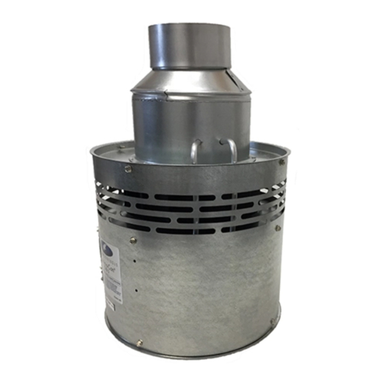
This product is designed for use with any oil burning furnace, water heater, or
boiler with 120 VAC control systems. It may also be used with more than one
appliance. The CAS unit mechanically draws air into a structure and
disperses it near the combustion air intake of an appliance. If an optional
Vacuum Relief Valve (VRV) is used, the incoming air is tempered before
entering the structure's airspace. Refer to Diagram A and B for guidance in
setting up the CAS system based on the size and length of the connecting
duct-work and the input rating of the appliance.
This device MUST be installed by a qualified agency in accordance with the manufacturers installation
instructions.
The definition of a qualified agency is: any individual, firm, corporation or company which either in person or through a
representative is engaged in, and is responsible for, the installation and operation of gas appliances, who is experienced
in such work, familiar with all the precautions required, and has complied with the requirements of the authority having
jurisdiction.
COMBUSTION AIR SYSTEM
Model: CAS-3
DO NOT DESTROY
THESE INSTRUCTIONS MUST REMAIN WITH EQUIPMENT
I
:
TEMS INCLUDED IN KIT
1)
Motorized Blower
1)
4" galvanized intake air Vent Hood
2)
Mounting brackets to secure the CAS to a wall
2)
Wire/conduit connector(s)
1)
4" x 6" Pipe Increaser Fitting
1)
6" Orifice Ring
1)
Instruction Sheet
1)
High/Low Motor Speed Switch
2630 Airport Road · Kinston, NC 28504
Phone: 252-522-3031· Fax: 252-522-0214
www.fieldcontrols.com
Advertisement
Table of Contents

Related Manuals for Field Controls 46261200


Summary of Contents for Field Controls 46261200
- Page 1 COMBUSTION AIR SYSTEM Model: CAS-3 TEMS INCLUDED IN KIT Motorized Blower 4" galvanized intake air Vent Hood Mounting brackets to secure the CAS to a wall Wire/conduit connector(s) 4" x 6" Pipe Increaser Fitting 6" Orifice Ring Instruction Sheet High/Low Motor Speed Switch This product is designed for use with any oil burning furnace, water heater, or boiler with 120 VAC control systems.
-
Page 2: General System Operation
GENERAL SYSTEM OPERATION 1. The thermostat (wall thermostat, or aquastat) calls for heat and energizes a relay which activates the CAS unit. After the CAS fan has come up to speed, an internal air pressure switch closes and completes the circuit to allow the burner to fire. If the appliance is power vented, the venter and CAS activate simultaneously. - Page 3 8. Draw a horizontal line on Diagram A or B that passes through the point located in step 5. The position of the point along this line relative to the left and right borders of the region it falls into indicates the relative position that the balance weight of the VRV should be adjusted to.
- Page 4 HIGH SPEED SIZING CHART OIL INPUT FIRING RATE (gallons per hour) (1 gallon oil/hr = 140,000 BTU/hr) 0.00 0.50 1.00 1.50 2.00 2.50 3.00 3.50 6" Duct & Hood 4" Duct & Hood 4" Duct, Hood, & Orifice GAS INPUT FIRING RATE (1000 BTU/hr.) Diagram A LOW SPEED SIZING CHART OIL INPUT FIRING RATE (gallons per hour)
-
Page 5: Installation
INSTALLATION CAS U LACEMENT OF THE The motorized CAS unit should be located on a flat horizontal surface within the space of the appliance or appliances, and try to be within 3 feet of the combustion air intake of the appliance. Two mounting brackets are provided for securing the unit against a solid structure, such as a wall, column, or the side of the appliance itself. -
Page 6: Wiring Instructions
The references to various series of control kits implies that any kit in that series may be used. If further information or additional wiring diagrams are needed please consult Field Controls' technical support. CAS U... - Page 7 Figure 6 – Riello Oil Fired System Figure 7 – Single Vent Oil Fired System Page 7...
- Page 8 Figure 8 – Chimney Vent Two Oil Fired System with CAC-120 Page 8...
-
Page 9: Maintenance
Figure 9 Figure 9 shows how the DIP-1 should be attached to the CAS. Note that the 1/4" O.D. plastic tubing on the top of the CAS unit must be cut and a 3-way male barb TEE suitable for 3/16" I.D. tubing placed as shown in order to connect the DIP-1. MAINTENANCE 1. -
Page 10: Replacement Parts
If this is necessary, take note of the positions and locations of whatever items that may need to be removed to replace other items. If in doubt, please consult the Field Controls Technical Support at 1-800-742-8368. Item Description... - Page 11 NOTES: Page 11...
- Page 12 Page 12 PN 46261200 Rev I 10/06...
Need help?
Do you have a question about the 46261200 and is the answer not in the manual?
Questions and answers