Table of Contents
Advertisement
Quick Links
TJERNLUND PRODUCTS, INC.
1601 Ninth Street • White Bear Lake, MN 55110-6794
PHONE (800) 255-4208 • (651) 426-2993 • FAX (651) 426-9547
Visit our web site • www.tjernlund.com
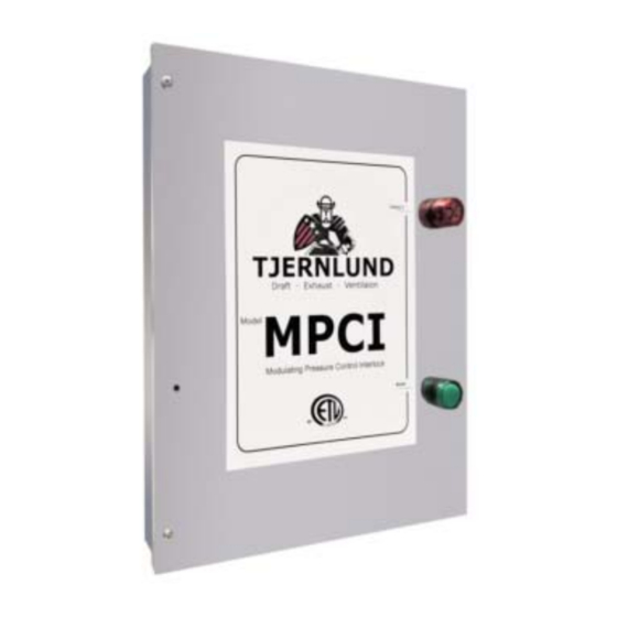
MODULATING PRESSURE CONTROL INTERLOCK
INSTALLATION INSTRUCTIONS
Recognize this symbol as an indication of important Safety Information!
!
OWNER INSTRUCTIONS, DO NOT DESTROY
WARNING
!
THESE INSTRUCTIONS ARE INTENDED AS AN AID TO QUALIFIED, LICENSED
SERVICE PERSONNEL FOR PROPER INSTALLATION, ADJUSTMENT AND
OPERATION OF THIS PRODUCT. READ THESE INSTRUCTIONS THOROUGHLY
BEFORE ATTEMPTING INSTALLATION OR OPERATION. FAILURE TO FOLLOW
THESE INSTRUCTIONS MAY RESULT IN IMPROPER INSTALLATION, ADJUST-
MENT, SERVICE OR MAINTENANCE POSSIBLY RESULTING IN FIRE, ELECTRI-
CAL SHOCK, CARBON MONOXIDE POISONING, EXPLOSION, PERSONAL
INJURY OR PROPERTY DAMAGE.
DO NOT DESTROY. PLEASE READ CAREFULLY AND
KEEP IN A SAFE PLACE FOR FUTURE REFERENCE.
Copyright © 2018, Tjernlund Products, Inc. All rights reserved
MODEL MPCI
REV 0618
P/N 8504243
Advertisement
Table of Contents

Summary of Contents for TJERNLUND MPCI
- Page 1 MENT, SERVICE OR MAINTENANCE POSSIBLY RESULTING IN FIRE, ELECTRI- CAL SHOCK, CARBON MONOXIDE POISONING, EXPLOSION, PERSONAL INJURY OR PROPERTY DAMAGE. DO NOT DESTROY. PLEASE READ CAREFULLY AND KEEP IN A SAFE PLACE FOR FUTURE REFERENCE. Copyright © 2018, Tjernlund Products, Inc. All rights reserved P/N 8504243...
-
Page 2: Table Of Contents
122 o F (50 o C) or 85% relative humidity. 3. The maximum wire distance from the Control to a VFD or ECM Exhaust Fan Motor is 300 feet. Install the MPCI as close to the pressure sampling point as possible to avoid delayed response to pressure changes. Do not exceed a sampling tube length of 15 feet (6 feet included with PSA-1 Fan Prover). -
Page 3: Sample And Reference Pressure Connections
Negative (Port Open) Recommendations based on MPCI Control being installed in the same room as the sample location. If the MPCI is installed in an adjacent space, pneumatic connections must be made to the open Pressure Ports that are indicated above. - Page 4 The goal is to reference static pressure. Don't sample pressures at locations that can be affected by frequently opened doors, elevator shafts, ventilation fans and diffusers. The model IPS-1 adjacent space Reference Pressure Sensor includes a decorative cover, sampling tube and fittings may be used in conjunction with the MPCI...
- Page 5 2. Connect a short length of tubing to the stainless steel sensing sampling tube. 3. Insert one end of the plastic T fitting included with the MPCI sampling tube packet into the end of the tubing installed in step 2.
-
Page 6: Make-Up / Combustion Air Pressure Set Point
U.S. or CSA C22.1-12 Canadian Electrical Code in Canada. All 120 V wiring from the MPCI to the Fan junction box must be appropriate Class 1 wiring as follows: installed in rigid metal con- duit, intermediate metal conduit, rigid non-metallic conduit, electrical metallic tubing, Type MI Cable, Type MC Cable, or be other- wise suitably protected from physical damage. - Page 8 10-minute period, the UC1 interlock will automatically reset and complete the circuit to the burner(s). The UC1 interlock will go into a hard lockout after 10 minutes without an automatic reset. Disrupting the call for heat or shutting off the MPCI internal 120 VAC power switch for 10 seconds will reset the UC1 interlock control.
- Page 9 P1 - P2 SAFETY CIRCUIT C, GND, F AUXILIARY DEVICE TERMINALS COMMUNICATION TERMINALS 1 mA @ 5VDC. 2 mA @ 5VDC. For Tjernlund MAC1E or SEE WARNING # 1. MAC4E auxiliary devices. SEE WARNING # 1. DIP SWITCH SETTINGS Pre-Purge (1-2)
- Page 10 IMPORTANT: UC1 Fault codes will automatically be displayed after a fault condition occurs. If the call for heat interlock signal or 115 VAC power is removed, the UC1 board will reset and the fault will be stored in memory instead of displayed. Any new fault will replace any previous fault.
- Page 11 The steps listed under each diagram are intended as a supplement to the diagram. Wiring colors or designations may vary by manufacturer. If you are unable to wire the UC1 as outlined in these instructions, call Tjernlund’s Customer Service Department toll free at 1-800-255-4208 for assistance.
-
Page 12: Wiring
After 10 seconds the UC1 interlock control should disrupt the circuit from terminal 4 to the burner(s). As long as there is a call for heat, the UC1 will continue to power the MPCI Pressure Control for 10 minutes. (If the pressure set point is not reached after 10 minutes, the UC1 will disrupt power to the Pressure Control and go into a hard lockout. -
Page 13: Adjusting Draft And Balancing Draft Of Heaters
-0.02 to -0.05" w.c. measured in the vent riser between the flue outlet and barometric draft control (if present). The MPCI has a default draft set point of -0.10" w.c. This vent manifold pressure may need to be adjusted up or down to meet the draft requirements of the interlocked heating equipment. - Page 15 This warranty does not cover normal maintenance, transportation or installation charges for replace- ment parts or any other service calls or repairs. This warranty DOES NOT cover the complete MPCI if it is operative, except for the defective part.


Need help?
Do you have a question about the MPCI and is the answer not in the manual?
Questions and answers