Table of Contents
Advertisement
Quick Links
M/B For Socket 370 Pentium
Trademark:
* Pentium is registered trademark and MMX is a trademark of Intel Corporation,
the other names and brands are the property of their respective owners
* Specifications and Information contained in this documentation are furnished for information use only, and are
subject to change at any time without notice, and should not be construed as a commitment by manufacturer.
635CS/635CN
USER'S MANUAL
NO. G03-635CSR1A
Release date: JULY 2001
** Year 2001 compliant **
III Processor
Advertisement
Table of Contents

Subscribe to Our Youtube Channel
Related Manuals for JETWAY 635CSR1A


Summary of Contents for JETWAY 635CSR1A
- Page 1 635CS/635CN USER'S MANUAL M/B For Socket 370 Pentium III Processor NO. G03-635CSR1A Release date: JULY 2001 ** Year 2001 compliant ** Trademark: * Pentium is registered trademark and MMX is a trademark of Intel Corporation, the other names and brands are the property of their respective owners * Specifications and Information contained in this documentation are furnished for information use only, and are subject to change at any time without notice, and should not be construed as a commitment by manufacturer.
-
Page 2: Table Of Contents
TABLE OF CONTENT USER’S NOTICE ................1 MANUAL REVISION INFORMATION ..........2 THERMAL SOLUTIONS ..............2 CHAPTER 1 INTRODUCTION OF 635CS/635CN MOTHERBOARD 1-1 FEATURE OF MOTHERBOARD ..........3 1-2 SPECIFICATION ..............4 1-3 PERFORMANCE LIST............. 5 1-4 LAYOUT DIAGRAM & JUMPER SETTING ........ 6 CHAPTER 2 HARDWARE INSTALLATION 2-1 HARDWARE INSTALLATION STEPS ........ - Page 3 3-7-2 ONCHIP DEVICE FUNCTION ..........33 3-7-3 ONBOARD SUPERIO DEVICE ..........34 3-8 POWER MANAGEMENT SETUP..........35 3-8-1 PM WAKE UP EVENTS............36 3-9 PNP/PCI CONFIGURATION SETUP .......... 37 3-9-1 IRQ RESOURCES ..............38 3-10 PC HEALTH STATUS ............. 39 3-11 MISCELLANEOUS CONTROL ..........40 3-12 LOAD STANDARD/OPTIMIZED DEFAULTS ......
-
Page 4: User's Notice
USER’S NOTICE COPYRIGHT OF THIS MANUAL BELONGS TO THE MANUFACTURER. NO PART OF THIS MANUAL, INCLUDING THE PRODUCTS AND SOFTWARE DESCRIBED IN IT MAY BE REPRODUCED, TRANSMITTED OR TRANSLATED INTO ANY LANGUAGE IN ANY FORM MEANS WITHOUT WRITTEN PERMISSION MANUFACTURER. THIS MANUAL CONTAINS ALL INFORMATION REQUIRED TO USE 635CS/635CN MOTHER-BOARD AND WE DO ASSURE THIS MANUAL MEETS USER’S REQUIREMENT... -
Page 5: Manual Revision Information
Manual Revision Information Reversion Revision History Date First Release July 2001 Item Checklist 635CS/635CN Cable for IDE/Floppy CD for motherboard utilities ¡ ¼ Cable for USB Port 3/4 (Option) 635CS/635CN User’s Manual Intel Processor Family Thermal Solutions As processor technology pushes to faster speeds and higher performance, thermal management becomes increasingly crucial when building computer systems. -
Page 6: Chapter 1 Introduction Of 635Cs/635Cn Motherboard
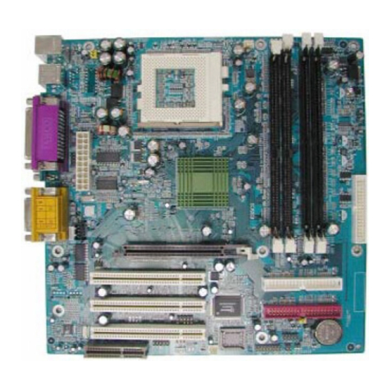
Chapter 1 Introduction of 635CS/635CN Motherboard 1-1 Feature of motherboard The 635CS/635CN motherboard is design for use Intel’s new generation Pentium processors, which utilize the Socket 370 design supports Pentium III/Tualatin /Celeron FC-PGA processors, and the memory size expandable to 1GB. This motherboard use the newest SiS 635 chipset provides a high performance/low cost solution for socket 370 series CPUs based system, by integrating a high performance North Bridge, Super-South Bridge and AGP4X Slot. -
Page 7: Specification
1-2 Specification Spec Description ∗ Micro ATX form factor 4 layers PCB size: 24.3 x 24.4.cm Design ∗ SiS 635 Chipset Chipset Clock Generator ∗ Support 66/100/133MHz system Bus Clock (CPU Bus Clock) Support 100/133 MHz system memory clock Support 33MHz PCI Bus clock ... -
Page 8: Performance List
1-3 Performance List The following performance data list is the testing result of some popular benchmark testing programs. These data are just referred by users, and there is no responsibility for different testing data values gotten by users (the different Hardware & Software configuration will result in different benchmark testing results.) ... -
Page 9: Layout Diagram & Jumper Setting
Float FPU/RAM MB/S QUAKE3 DEMO1 109.7 109.4 117.6 DEMO2 104.7 104.3 112.5 1-4 Layout Diagram & Jumper Setting PRINT GAME/MIDI PORT (Only for 635CS) PS/2 MOUSE PS/2 Keyboard LINE-IN COM1 COM2 LINE-OUT CPU FAN (JP1, JP2) USB Power On CPU F.S.B. Clock function (JP3) Keyboard Power On function (JP4) -
Page 10: Expansion Sockets
Jumpers Jumper Name Description Page JP1, JP2 CPU Front Side Bus Frequency Setting 1x2-pin Block 2x4-pin Block USB Power ON Function Setting 3-pin Block Keyboard Power ON Function Setting 3-pin Block CMOS RAM Clear 3-pin Block Connectors Connector Name Description Page ATX Power Connector 20-pin Block... -
Page 11: Chapter 2 Hardware Installation
PCI _ 3 AGP Slot AGP Expansion Slot p.16 CNR Slot Communication Riser card Slot Chapter 2 Hardware installation 2-1 Hardware installation Steps Before using your computer, you had better complete the following steps: 1. Check motherboard setting 2. Install CPU 3. - Page 12 2. USB Power On Function Setting (3-pin): JP3 This allows you to disable the USB power on function. Set the jumper to enabled or disabled if you wish to use your USB Device to power on your computer. This feature requires an ATX power supply that can supply at least 300mA on the +5VSB lead.
-
Page 13: Install Cpu
1. Troubleshooting 2. Forget password 3. After over clocking system boot fail 1-2 closed Clear CMOS 2-3 closed Normal (default) CMOS RAM Clear Setting 2-3 Install CPU 2-3-1 About Pentium III & Celeron™ 370-pin CPU This motherboard supports both Pentium III & Celeron 370 pins CPU. Glossary: Chipset (or core logic) - two or more integrated circuits which control the interfaces between the system processor, RAM, I/O devises, and adapter cards. - Page 14 establish the relationship between the various components. Driver - software, which defines the characteristics of a device for use by another device or other software. Processor – the "central processing unit" (CPU); the principal integrated circuit used for doing the "computing" in "personal computer" Front Side Bus Frequency The working frequency of the motherboard, which is generated by the clock generator for CPU, DRAM and PCI BUS.
-
Page 15: Install Cpu
2-3-2 Setting CPU Bus Clock Jumper Setting the front side bus frequency The motherboard uses jumper JP5 for the front side bus frequency setting as shown from the table below: CPU/SDRAM (MHz) AUTO 100M 133M III 866 CPU with front side bus frequency of 133MHz Example: Using a Pentium and PC-133 SDRAM module, the setting of JP5 are 1-2 open, 3-4 open, 5-6... -
Page 16: Overclock Running
Intel Pentium III Colden Arrow CPU ZIF Socket 370 When you put the CPU into the ZIF socket. No force require to insert of the CPU, then press the level to Locate position slightly without any extra force. 2-3-4 Over clock Running WARNING! This section is for experienced motherboard installer only. -
Page 17: Install Memory
Auto Detect DIMM/PCI Clk Enabled Item Help CPU Host/DRAM Clock Spread Spectrum Disabled CPU Host/DRAM/PCI Clock Default Default CPU Clock Ratio Jumpless By H/W 66/66/33MHz ..Menu Level > 66/100/33MHz ..100/100/33MHz ..CyrixIII CPU Ratio 101/101/34MHz ..Adjust 103/103/34MHz .. -
Page 18: Expansion Card
Figure 2-4 NOTE! When you install DIMM module fully into the DIMM socket the eject tab should be locked into the DIMM module very firmly and fit into its indention on both sides. WARNING! For the SDRAM CLOCK is set at 133MHz, use only PC133 /PC2100-compliant DIMMs. -
Page 19: Assigning Irq For Expansion Card
2-5-2 Assigning IRQs For Expansion Card Some expansion cards need an IRQ to operate. Generally, an IRQ must exclusively assign to one use. In a standard design, there are 16 IRQs available but most of them are already in use. Standard Interrupt Assignments Priority Standard function... -
Page 20: Agp Slot
2-5-4 AGP Slot This motherboard provides an AGP Slot, support the 1X/2X/4X AGP VGA card. AGP SLOT 2-6 Connectors, Headers 2-6-1 Connectors Power Connector (20-pin block): U11 ATX Power Supply connector. This is a new defined 20-pins connector that usually comes with ATX case. - Page 21 Parallel Port connector is a 25-pin D-Subminiature Receptacle connector. The On-board Parallel Port can be disabled through the BIOS SETUP. Please refer to Chapter 3 “INTEGRATED PERIPHERALS SETUP” section for more detail information. Audio and Game Connector : GAME This Connector are 3 phone Jack for LINE-OUT, LINE-IN, MIC and a 15-pin D-Subminiature Receptacle Connector for joystick/MIDI Device.
-
Page 22: Headers
second drive to Slave mode by setting its jumpers accordingly. Please refer to the documentation of your hard disk for the jumper settings. Pin 1 Primary IDE Connector (11) Secondary IDE Connector (40-pin block): IDE2 This connector connects to the next set of Master and Slave hard disks. Follow the same procedure described for the primary IDE connector. - Page 23 USB2 Pin 1 USB Port Connector IDE Activity LED: IDE LED This connector connects to the hard disk activity indicator light on the case. Turbo LED switch: TURBO LED Since the motherboard’s turbo function is always on. The turbo LED will remain constantly on while the system power is on.
- Page 24 Wake On-LAN Headers (3-pin): WOL This connector connects to a LAN card with a WAKE ON-LAN output. This connector power up the system when a wake up signal is received through the LAN card. NOTE: This feature requires that Wake On LAN or Ring In Wake up is enabled. Wake-On-LAN Headers FAN Speed Headers (3-pin): CPUFAN, SYSFAN These connectors support cooling fans of 350mA (4.2 Watts) or less, depending...
-
Page 25: Starting Up Your Computer
CDIN1 and CDIN2 are the connectors for CD-Audio Input signal. Please connect it to CD-ROM CD-Audio output connector. CDIN2 CDIN1 CD Audio-In Headers (12) Front Panel Line-In, Line-Out, MIC Headers: AUDIO AUDIO Pin 1 Line-In/Out, MIC Headers 2-7 Starting Up Your Computer 1. -
Page 26: Chapter 3 Introducing Bios
c. Your system power. For ATX power supplies, you need to turn on the power supply and press the ATX power switch on the front side of the case. 5. The power LED on the front panel of the system case will light. The LED on the monitor may light up or switch between orange and green after the system is on. -
Page 27: Entering Setup
to communicate, it is the key factor for system stability, and in ensuring that your system performance as its best. In the BIOS Setup main menu of Figure 3-1, you can see several options. We will explain these options step by step in the following pages of this chapter, but let us first see a short description of the function keys you may use here: •... -
Page 28: The Main Menu
3-3 The Main Menu Once you enter Award BIOS CMOS Setup Utility, the Main Menu (Figure 3-1) will appear on the screen. The Main Menu allows you to select from fourteen setup functions and two exit choices. Use arrow keys to select among the items and press <Enter>... -
Page 29: Standard Cmos Features
This entry shows your PC health status. Miscellaneous Control Use this menu to specify your settings for frequency/voltage control. Load Optimized Defaults Use this menu to load the BIOS default values that are factory settings for optimal performances system operations. Load Standard Defaults Use this menu to load the BIOS default values for the minimal/stable performance system operation. -
Page 30: Advanced Bios Features
> IDE Primary Master Press Enter None Menu Level > > IDE Primary Slave Press Enter None > IDE Secondary Master Press Enter None Change the day, month, > IDE Secondary Slave Press Enter None year and century Drive A 1.44M, 3.25 in. -
Page 31: Virus Warning
CMOS Setup Utility – Copyright(C) 1984-2001 Award Software Advanced BIOS Features Anti-Virus Protection Disabled Item Help Recovery Genius Enabled PhoenixNet Support Disabled CPU L1 Cache Enabled Menu Level > CPU L2 Cache Enabled CPU L2 Cache ECC Checking Disabled Allows you to choose Processor Number Feature Enabled The VIRUS warning... - Page 32 CPU L2 Cache ECC Checking Choose Enabled or Disabled. This option enables the Level 2 cache memory ECC (error check correction). Processor Number Feature This option is for Pentium III processor. During Enabled, this will check the CPU Serial number.
-
Page 33: Security Option
Typematic Delay (Msec) Sets the delay time after the key is held down before is begins to repeat the keystroke. The settings are 250, 500, 750, and 1000. Security Option This category allows you to limit access to the system and Setup, or just to Setup. System The system will not boot and access to Setup will be denied if the correct password is not entered at the prompt. -
Page 34: Dram Timing Settings
AGP Function Settings Please refer to section 3-6-2 System BIOS Cacheable Selecting Enabled allows caching of the system BIOS ROM at F0000h-FFFFFh, resulting in better system performance. However, if any program writes to this memory area, a system error may result. The settings are: Enabled and Disabled. Video RAM Cacheable Select Enabled allows caching of the video BIOS, resulting in better system performance. -
Page 35: Integrated Peripherals
CMOS Setup Utility – Copyright(C) 1984-2001 Award Software AGP Function Settings AGP Transfer Mode Auto Item Help AGP Fast Write Disabled AGP Aperture Size 64MB AGP Aperture Write Combining Enabled Menu Level >> AGP Driving Control Auto X AGP Driving Value Move Enter:Select +/-/PU/PD:Value F10:Save ESC:Exit F1:General Help ¡... -
Page 36: Onchip Ide Function
Init Display First This item allows you to decide to activate whether PCI Slot or AGP VGA first. The settings are: PCI Slot, AGP Slot. 3-7-1 OnChip IDE Function CMOS Setup Utility – Copyright(C) 1984-2001 Award Software OnChip IDE Function Internal PCI/IDE Both Item Help... -
Page 37: Onchip Device Function
Block mode is also called block transfer, multiple commands, or multiple sector read/write. If your IDE hard drive supports block mode (most new drives do), select Enabled for automatic detection of the optimal number of block read/writes per sector the drive can support. -
Page 38: Onboard Parallel Port
CMOS Setup Utility – Copyright(C) 1984-2001 Award Software Onboard SuperIO Device Onboard FDD Controller Enabled Item Help Onboard Serial Port 1 3F8/IRQ4 Onboard Serial Port 2 2F8/IRQ3 UART 2 Mode Normal Menu Level >> RxD,TxD Active Hi,Hi IR Transmission Delay Enabled IR Duplex Mode Half... -
Page 39: Power Management Setup
To operate the onboard parallel port as Standard Parallel Port only, choose “SPP.” To operate the onboard parallel port in the EPP modes simultaneously, choose “EPP.” By choosing “ECP”, the onboard parallel port will operate in ECP mode only. Choosing “ECP+EPP”... -
Page 40: Pm Wake Up Events
DPMS (default) Initial display power management signaling. Blank Screen This option only writes blanks to the video buffer. V/H SYNC+Blank This selection will cause the system to turn off the vertical and horizontal synchronization ports and write blanks to the video buffer. -
Page 41: Pnp/Pci Configuration Setup
This will enable the system to wake up by PCI device Power Management function. The settings are: Enabled and Disabled. KB Power ON Password This item can setting Power On Password, if you Enabled keyboard Power On function then you can Power On system by key-in the password which you setting. Power Up by Alarm This function is for setting date and time for your computer to boot up. -
Page 42: Reset Configuration Data
Reset Configuration Data Normally, you leave this field Disabled. Select Enabled to reset Extended System Configuration Data (ESCD) when you exit Setup if you have installed a new add-on and the system reconfiguration has caused such a serious conflict that the operating system can not boot. The settings are: Enabled and Disabled. -
Page 43: Pc Health Status
3-10 PC Health Status This section shows the Status of you CPU, Fan, Warning for overall system status. This is only available if there is Hardware Monitor onboard. CMOS Setup Utility – Copyright(C) 1984-2001 Award Software PC Health Status CPU Warning Temperature Disabled Item Help Shutdown Temperature... -
Page 44: Miscellaneous Control
3-11 Miscellaneous Control This section is for setting CPU Frequency Control. CMOS Setup Utility – Copyright(C) 1984-2001 Award Software Miscellaneous Control Auto Detect DIMM/PCI Clk Enabled Item Help Spread Spectrum Disabled CPU Host/DRAM/PCI Clock Default Menu Level > CPU Clock Ratio Jumpless By H/W CyrixIII CPU Ratio Adjust... -
Page 45: Set Supervisor/User Password
3-13 Set Supervisor/User Password You can set either supervisor or user password, or both of them. The differences are: Supervisor password: Can enter and change the options of the setup menus. User password: Can only enter but do not have the right to change the options of the setup menus. -
Page 46: Chapter 4 Driver & Free Program Installation
Chapter 4 DRIVER & FREE PROGRAM INSTALLATION Check your package and there is A MAGIC INSTALL CD included. This CD consists of all DRIVERS you need and some free application programs and utility programs. In addition, this CD also include an auto detect software which can tell you which hardware is installed, and which DRIVERS needed so that your system can function properly. -
Page 47: Agpvxd
4-1 AGPVXD Install SiS AGPVXD Driver The AGPVXD Driver is Only For AGP Slot VGA CARD User, before install AGP card driver please install this AGPVXD driver first. The path of the file: for WINDOWS 9X is X:\SIS635\AGPVXD\WIN9X\SETUP.EXE (including WIN95/98/98SE/ME) for WINDOWS 2000 is X:\SIS635\AGPVXD\WIN2000\SETUP.EXE For WINDOWS 95/98/98SE/ME/2000 1. -
Page 48: Sound Ac97 Sound Driver And The Program Install
4-2 SOUND AC97 sound driver and the program install for editing/playback 1. Click SOUND when MAGIC INSTALL 2. Then auto detect operation system MENU appears language edition, click OK, start to install DRIVER 3. When ask Remove old device driver, 4. -
Page 49: Lan (Only For 635Cs) Install Sis 900 Pci Fast Ethernet Driver
4-3 LAN (Only for 635CS) Install SiS 900 PCI Fast Ethernet Driver The path of the file: for WINDOWS 9X/2000 is X:\SIS635\LANDRV\SETUP.EXE (Including WINDOWS 95/98/98SE/98ME/2000) for WINDOWS NT4.0 is X:\SIS635\LANDRV\NT40 WINDOWS 95/98/98SE/98ME/2000 Setup 1. Click LAN when Magic Install Menu 2. -
Page 50: Pc-Health Winbond Hardware Doctor Monitoring Software
4-4 PC-HEALTH Winbond Hardware Doctor Monitoring Software The path of the file is X:\SIS635\HEALTH-W\SETUP.EXE (Only support WINDOWS 95/98/98SE/ME) In Windows 95/98 Winbond Hardware Doctor Monitoring Software needs some system files to copy in Utility that’s why it needs install PC-HEALTH twice to complete setup. 1. -
Page 51: How To Utilize Pc-Health
4-4-1 How To Utilize PC-HEALTH 2. After executing Winbond Hardware 1. Click Program → Winbond Hardware Doctor it supports system voltage, Fan Doctor → Hardware Doctor the speed and CPU/SYSTEM Temperature. Winbond Hardware Doctor will appears Because this is a On-time Monitoring You can remove the Utility in Control program therefore the value will change Panel →... - Page 52 After finish Setup you will have a Double click the Magic BIOS icon you Magic BIOS icon in your screen will have this picture, choose from internet you can upgrade BIOS On-line When On-line update BIOS the program Click Next if you need update BIOS, will auto-check your BIOS version after upgrade BIOS, the system will clear CMOS and automatically restart...
-
Page 53: Pc-Cillin
When choose From Local Driver to update 10. Choose the correct BIOS file to update BIOS BIOS, you must have the correct BIOS file in your Local Driver 4-6 PC-CILLIN Install PC-CILLIN 2000 Anti-virus program 1. Click PC-CILLIN when MAGIC INSTALL 2. - Page 54 5. Click OK and If You Have Proxy Server, 6. Click NEXT when Start Copy Files, Start to Enter Your Setting install the software 7. If you want to make a rescue disc, insert a 8. Setup Complete and click Finish 1.44 MB disc 9.
-
Page 55: How To Disable On-Board Sound
4-7 How To Disable On Board Sound Function Please key in “DEL” key after power on to enter BIOS SETUP screen and choose Integrate Peripherals → On-Chip Device Function → AC97 Audio item to disabled all on board Sound function by Page Down key. 4-8 HOW To Update BIOS STEP 1.
Need help?
Do you have a question about the 635CSR1A and is the answer not in the manual?
Questions and answers