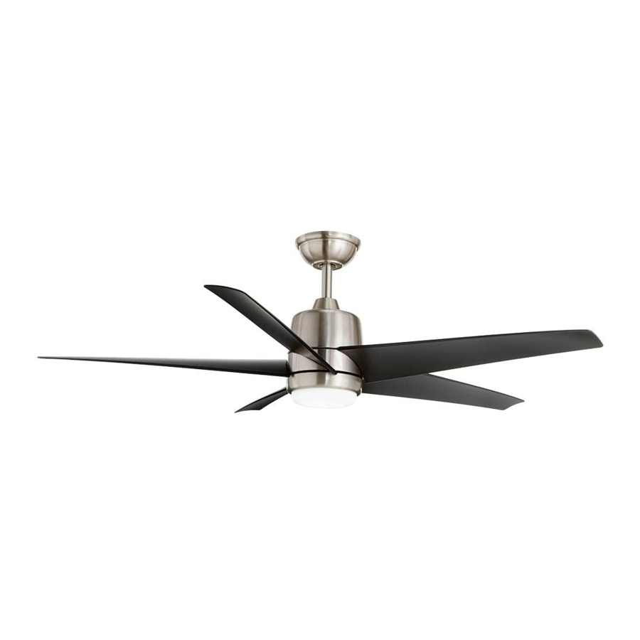
HAMPTON BAY MENA, 32318, 32319, 268 528, 267 493 Manual
- Use and care manual (15 pages)
- Also fits for
- 32318
- 32319
- 268 528
- 267 493
Advertisement
Pre-Installation
SPECIFICATIONS
| Size | Speed | Volts | Fan Power Consumption (without lights) WATT | Airflow CFM | Airflow Efficiency (Higher Is Better) CFM/WATT | Net Weight | Gross Weight | Cubic Feet |
| 54 in. | Low | 120 | 13 | 2,053 | 157 | 17.97 lbs (8.15 kg) | 21.01 lbs (9.53 kg) | 1.87 cu. ft. |
| Medium | 32 | 3,629 | 113 | |||||
| High | 60 | 5,246 | 87 |
NOTE: These are approximate measures. They do not include the Amps and Wattage used by the light kit.
TOOLS REQUIRED

HARDWARE INCLUDED
NOTE: Hardware not shown to actual size.

| Part | Description | Quantity |
| AA | Plastic wire connecting nuts | 3 |
| BB | Hanger pin | 1 |
| CC | Locking pin | 1 |
PACKAGE CONTENTS

| Part | Description | Quantity |
| A | Slide-on mounting bracket (inside canopy) | 1 |
| B | Ball/downrod assembly | 1 |
| C | Canopy | 1 |
| D | Decorative motor collar cover | 1 |
| E | Fan-motor assembly | 1 |
| F | Blade | 5 |
| G | Light kit assembly | 1 |
| I | Receiver | 1 |
| J | Remote control | 1 |
| K | Extension lead wire | 1 |
| L | Battery | 1 |

This product and/or components are governed by one or more of the following U.S. Patents: 5,947,436; 5,988,580; 6,010,110; 6,046,416; 6,210,117 and other patents pending.
Installation
MOUNTING OPTIONS

To reduce the risk of fire, electric shock or personal injury, mount to outlet box marked "Acceptable for fan support of 35 lbs. (15.9 kg) or less", and use screws provided with the outlet box. An outlet box commonly used for the support of lighting fixtures may not be acceptable for fan support and may need to be replaced. If in doubt, consult a qualified electrician.
If your ceiling fan does not have an existing UL-listed mounting box, then install one using the following instructions:
- Disconnect the power by removing the fuses or turning off the circuit breakers.
- Secure the outlet box directly to the building structure. Use the appropriate fasteners and materials. The outlet box and support structure must be securely mounted and capable of reliably supporting a minimum of 35 lbs. (15.9 kg). Use only UL-listed outlet boxes marked "Acceptable for fan support of 35 lbs. (15.9 kg) or less" Do not use a plastic outlet box.
The illustrations below show three different ways to mount the outlet box.

NOTE: You may need a longer downrod to maintain proper blade clearance when installing on a steep, sloped ceiling. The maximum angle allowable is 30° away from horizontal.
If the canopy touches the downrod, then remove the decorative canopy bottom cover, and turn the canopy 180° before attaching the canopy to the mounting plate.
To hang your fan where there is an existing fixture but no ceiling joist, you may need an installation hanger bar as shown below (available at any Home Depot store).

Assembly
Standard Ceiling Mount
- Preparing for mounting

- Remove the canopy ring (FF) from the canopy (C) by turning the ring counter clockwise until it unlocks.
- Remove the mounting bracket (A) from the canopy (C) by loosening the two canopy screws (II) located in the "L shaped" slots.
- Remove and save the two canopy screws (HH) in the round holes. This will enable you to remove the mounting bracket (A)
- Routing the wires
![]()
- Route the wires exiting the top of the fan motor assembly (E) through the center of the canopy ring (FF). Make sure the slots on the canopy ring (FF) are on top.
- Insert the ball/downrod (B) through the canopy (C) and slide the decorative motor collar cover (D) onto the end of the ball/ downrod (B). Make sure the slots on the canopy (C) are on top.
- Route the wires exiting the top of the fan motor assembly (E) through the downrod (B) as shown.
- Assembling the fan
![]()
Failure to properly install the locking pin (CC) could result in the fan becoming loose and possibly falling.
![]()
To ensure wobble-free operation and to avoid damage to the fan, the downrod (B) and the setscrew (JJ) must be completely tightened.

- Loosen, but do not remove, the setscrews (JJ) on the collar on top of the fan-motor assembly (E).
- Align the holes at the bottom of the ball/downrod assembly (B) with the holes in the collar on top of the fan-motor assembly (E).
- Carefully insert the hanger pin (BB) through the holes in the collar and ball/downrod assembly (B). Be careful not to jam the hanger pin (BB) against the wiring inside the ball/downrod assembly (B).
- Insert the locking pin (CC) through the hole near the end of the hanger pin (BB) until it snaps into its locked position.
- Re-tighten the setscrews (JJ) on the collar on top of the fan-motor assembly (E).


Hanging the Fan
- Attaching the fan to the electrical box
![]()
To reduce the risk of fire, electric shock or personal injury, mount to outlet box marked "Acceptable for fan support of 35 lbs. 15.9 kg) or less", and use screws provided with the outlet box.
NOTE: The mounting bracket (A) is designed to slide into place on an outlet box with the outlet box screws (TT) installed.

- Loosen the two mounting screws (TT) in the outlet box.
- Pass the 120-Volt supply wires through the center hole in the mounting bracket (A).
- Slide the mounting bracket (A) on to the mounting screws (TT) and center the mounting bracket (A) in relation to the outlet box. If necessary, use leveling washers (not included) between the slide-on mounting bracket (A) and the outlet box. The flat side of the slide-on mounting bracket (A) should face toward the outlet box, as shown.
- Securely tighten the two mounting screws (TT).
- Hanging the fan

- Carefully lift the fan-motor assembly (E) up to the slide-on mounting bracket (A).
- Insert the ball portion of the ball/downrod assembly into the socket of the slide-on mounting bracket (A).
- Turn the ball/downrod (B) assembly clockwise until it is seated with the tab of the slide-on mounting bracket (A) aligned with the slot in the ball.
- Preparing the remote control
NOTE: The remote control has already been paired to the ceiling fan for your convenience. If you have two of the same model fans in your home, please follow the steps below to control each fan independently.
NOTE: The remote control battery will weaken with age and should be replaced before leaking takes place, as this will damage the remote control. Dispose of used battery properly and keep the battery out of the reach of children.- Confirm that the power to the fan is off at either the wall switch or breaker box.
- Remove the battery cover by pressing firmly on the arrow and sliding the cover off.
- Install the 23A battery (0).
- Return power to the fan at the wall switch or breaker box.
- Press and release the "Learn" button for 1-2 seconds, located in the remote's battery compartment within 30 seconds of turning on the power.
- If pairing is successful, the fan's light kit will flash and the blades will begin to spin.
- Replace the battery cover on the remote control.


1 to 3 mode
- To use more than one remote control for your fan, press the "Learn" button for 10 seconds and release within 30 seconds of turning on the power. Once pairing is successful, the fan's light kit will flash and the blades will begin to spin.
- Repeat the above process for the remote controls you want to work with this fan.
- The fan can be only controlled by 3 remote controls maximum at the same time after "Learning". If you use a forth remote control to handle the fan, the first remote control will be replaced.
1 to 1 mode
- To use only one remote control for your fan, press and release the "Learn" button for 1-2 seconds within 30 seconds of turning on the power. The "1 to 3" mode will be cleared and returned back to "1 to 1" mode.


- Installing the receiver
![]()
To reduce the risk of fire or electric shock, remember to disconnect power. The electrical wiring must meet all local and national electrical code requirements. The electrical source and fan must be 110/120 volt, 60Hz. Do not use this product in conjunction with any variable wall control. Incorrect wire connection can damage this receiver.
![]()
If other fan wires are a different color, have this unit installed by a licensed electrician.
![]()
Do not install the receiver in a damp location or immerse in water (For indoor use only). Do not pull on or cut the receiver leads shorter. Do not drop or bump the unit.

- Position the house supply wires (AAA) to one side of the slide-on mounting bracket (A); position the fan wires (BBB) to the opposite side.
- Insert the narrow end of the receiver (I) (as shown, flat side towards the ceiling) into the slide-on mounting bracket until it rests on top of the ball/downrod assembly.
- Wiring the receiver to the household wiring
![]()
To avoid possible electrical shock, turn the electricity off at the main fuse box before wiring. If you feel you do not have enough electrical wiring knowledge or experience, contact a licensed electrician.
![]()
Each wire nut supplied with this fan is designed to accept up to one 12-gauge house wire and two wires from the fan. If you have larger than 12-gauge house wiring or more than one house wire to connect to the fan wiring, consult an electrician for the proper size wire nuts to use.
![]()
Use the wire connecting nuts (AA) supplied with your fan. Secure the connectors with electrical tape and ensure there are no loose strands or connections.

- Spread the wires apart so that the green and white wires are on one side of the outlet box and the black wire is on the other side.
- Connect the green fan wires to the household ground wire (this may be a green or bare wire) using a wire connecting nut (AA).
- Connect the receiver (I) black or red wire to the household black (hot) wire using a wire connecting nut (AA).
- Connect the receiver (I) white wire to the household white wire (neutral) using a wire connecting nut (AA).
- Secure each wire connecting nut using electrical tape.
- Wiring the fan to the receiver
NOTE: The fan comes with 8 in. lead wires for use with the provided 6 in. ball downrod assembly (B). If you wish to use longer downrod, you can use the extension lead wire (42 in.) (K) provided.

- If using the 6 in. ball downrod assembly (B) provided, wire the receiver to the fan wires by connecting the molded adaptor plug from receiver (I) with molded adaptor of the fan motor assembly (E) together.
- If you wish to use longer downrod, you can use the extension lead wire (42 in.) (K) provided by connecting the molded adaptor together.
- Mounting the fan-motor assembly (standard mount)

- Align the locking slots of the canopy (C) with the two screws (II) in the mounting bracket (A). Push up to engage the slots and turn clockwise to lock in place.
- Firmly tighten the two mounting screws (II).
- Install the two canopy screws (HH) (saved from Assembly Step 1 "Preparing for mounting") into the holes in the canopy (C) and tighten firmly.
- Install the decorative canopy ring (FF) by aligning the ring's slots with the screws in the canopy (C). Rotate the ring clockwise to lock in place.


Attaching the Fan Blades
- Attaching the blades to the motor
NOTE: Blade installation must be properly completed before attaching the light kit.
![]()
- Attach a blade (F) to the fan motor assembly (E) by inserting the blade (F) into the slot in the side of the fan motor housing (E) until it stops. The locking clip (LL) will click when the blade is correctly installed. Ensure the blade is snapped into locking clip (LL) completely by pulling the fan blade away from the motor housing.
- Repeat these steps for the remaining blades (F).

Removing the blades from the motor
NOTE: Make sure you have turned the black plate with notch towards the blade you would like to remove.

Attaching the Accessories
- Attaching the light kit fitter assembly

- Connect the wires from the light kit assembly (G) to the wires from the fan motor assembly (E) by connecting the molded adaptor plugs together. Carefully tuck all wires and splices into the switch cup and connect the safety cable (SS) from the light kit assembly (G) to the hook from motor assembly (E).
- Push the light kit assembly (G) up to the motor assembly (E) by aligning the magnet part of the motor assembly (E) till it is secure.

Operating Your Fan and Remote Control
Remote Control - Your fan is equipped with a remote control to operate the speed and lights of your new ceiling fan.
Speed setting for warm or cool weather depends on factors such as the room size, ceiling height, number of fans and so on.
The fan is shipped from the factory with the reversing switch (YY) positioned to circulate air downward. If airflow is desired in the opposite direction, turn your fan off and wait for the blades to stop turning, then slide the reversing switch (located on the top of the motor housing) to the opposite position, and turn the fan on again. The fan blades will turn in the opposite direction and reverse airflow.

Warm weather - (Forward) A downward airflow creates a cooling effect. This allows you to set your air conditioner on a higher setting without affecting your comfort.
Cool weather - (Reverse) An upward airflow moves warm air off of the ceiling. This allows you to set your heating unit on a lower setting without affecting your comfort.

 Power ON/OFF: Press and release the power button to turn the fan and light on or off.
 Fan speed: LEDs on the fan speed button will illuminate to the corresponding speed.
Press and release 1 time: turns the fan on high speed.
Press and release 2 times: turns the fan on medium speed.
Press and release 3 times: turns the fan on low speed.
Press and release 4 times: turns the fan off.
 Light ON/OFF
Press and release the button to turn the light on or off.
Press and hold the button to activate the dimmer function.
 Correlated Color Temperature (CCT) changing
NOTE: The default temperature of the ceiling fan light is 3000k (Soft White).
Push and release the button to cycle through the three color temperature options.
Option 1: 2700K (Warm White).
Option 2: 3000K (Soft White).
Option 3: 5000K (Daylight).
Care and Cleaning

Make sure the power is off before cleaning your fan.
- Because of the fan's natural movement, some connections may become loose. Check the support connections, brackets, and blade attachments twice a year. Make sure they are secure. It is not necessary to remove the fan from the ceiling.
- Clean your fan periodically to help maintain its new appearance over the years. Do not use water when cleaning, as this could damage the motor, or the wood, or possibly cause an electrical shock. Use only a soft brush or lint-free cloth to avoid scratching the finish.
- You can apply a light coat of furniture polish to the wood for additional protection and enhanced beauty. Cover small scratches with a light application of shoe polish.
- You do not need to oil your fan. The motor has permanently-lubricated sealed ball bearings.
- To remove the blade from the motor housing, squeeze the tabs of the locking clip towards each other and pull the fan blade away from the motor housing.
Troubleshooting
| Problem | Solution |
| The fan will not start. |
|
| The fan is noisy. |
|
| The fan wobbles. |
|
Safety Information
READ AND SAVE THESE INSTRUCTIONS.
- To reduce the risk of electric shock, ensure the electricity has been turned off at the circuit breaker or fuse box before you begin.
- All wiring must be in accordance with the National Electrical Code ANSI/NFPA 70 and local electrical codes. Electrical installation should be performed by a qualified licensed electrician.
- The outlet box and support structure must be securely mounted and capable of reliably supporting a minimum of 35 lbs. (15.9 kg). Use only UL-listed outlet boxes marked "Acceptable for Fan Support of 35 lbs. (15.9 kg) or less."
- The fan must be mounted with a minimum of 7 ft (2.1 m) of clearance from the trailing edge of the blades to the floor.
- Do not place objects in the path of the blades.
- To avoid personal injury or damage to the fan and other items, use caution when working around or cleaning the fan.
- After making electrical connections, spliced conductors should be turned upward and pushed carefully up into the outlet box. The wires should be spread apart with the grounded conductor and the equipment-grounding conductor on one side of the outlet box.
- All set screws must be checked and retightened where necessary before installation.
To reduce the risk of personal injury, do not bend the blade brackets (also referred to as flanges) during assembly or after installation. Do not insert objects in the path of the blades.
To reduce the risk of fire or electric shock, do not use this fan with any solid-state speed control device.
To avoid possible electrical shock, turn the electricity off at the main fuse box before wiring. If you feel you do not have enough electrical wiring knowledge or experience, contact a licensed electrician.
To reduce the risk of fire, electric shock or personal injury, mount to outlet box marked "Acceptable for fan support of 35 lbs. (15.9 kg) or less", and use screws provided with the outlet box.
Electrical diagrams are for reference only. If you are using a light kit, refer to the light kit instructions manual to make the electrical connections. Optional use of any light kit shall be UL-listed and marked suitable for use with this fan.
To reduce the risk of fire or electric shock, this fan should only be used with fan speed control part no. AL-3L, manufactured by DawnSun Electronic Technology Co., Ltd. Zhongshan.
To reduce the risk of electric shock, this fan must be installed with an isolating wall switch.

To reduce the risk of personal injury, use only the screws provided with the outlet box.
Do NOT use this fan with a dimmer switch or wall control. Using a dimmer switch or wall control will damage the fan.
Changes or modifications not expressly approved by the party responsible for compliance could void the user's authority to operate the equipment.
Questions, problems, missing parts?
Please call Customer Service
8 a.m. - 6 p.m., EST, Monday-Friday.
1-800-431-3000
Documents / ResourcesDownload manual
Here you can download full pdf version of manual, it may contain additional safety instructions, warranty information, FCC rules, etc.
Download HAMPTON BAY MENA, 32318, 32319, 268 528, 267 493 Manual
Advertisement


Need help?
Do you have a question about the MENA and is the answer not in the manual?
Questions and answers