
Related Manuals for HAMPTON BAY Minuet III


Summary of Contents for HAMPTON BAY Minuet III
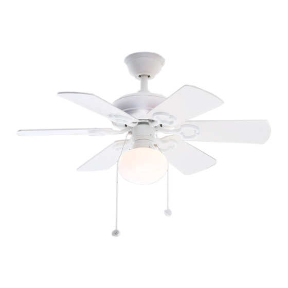
- Page 1 Minuet III Ceiling Fan Owner's Manual Minuet III Ventilador de Techo de 0.91 Manual del Propietario...
- Page 2 Hampton Bay Lifetime Motor Warranty The retailer warrants the fan motor to be free from defects in workmanship and material present at time of shipment from the factory for a lifetime after the date of purchase by the Date Purchased original purchaser.
-
Page 3: Table Of Contents
Safety Rules............................. Unpacking Your Fan ........................... Installing Your Fan ..........................Installing the Light Kit........................Operating Your Fan .......................... Care of Your Fan ..........................Troubleshooting ..........................Specifications ..........................Table of Contents... -
Page 4: Safety Rules
1.To reduce the risk of electric shock, insure electricity has been 8. Avoid placing objects in the path of the blades. turned off at the circuit breaker or fuse box before beginning. 9. To avoid personal injury or damage to the fan and other items, be cautious when working around or cleaning the fan. -
Page 5: Unpacking Your Fan 2
Unpack your fan and check the contents. You should have the following items: Set of blades (6) 13. Loose parts bag containing: Light fixture 2. Canopy assembly a. Blade attachment hardware Glass shade Ball/downrod assembly (19 screws) Pull chain and fobs (2) Coupling cover b. -
Page 6: Tools Required
Tools Required Angled ceiling maximum P h i l l i p s s c r e w d r i v e r, s t r a i g h t s l o t 20 angle Provide strong support screwdriver, step ladder, and wire cutters. -
Page 7: Hanging The Fan
he holes in the collar and downrod. non-slotted screws and loosen the slotted Hanging the Fan careful not to jam the pin against the screws. This will enable you to remove wiring inside the downrod. Insert the the hanger bracket. (Fig. 5) locking pin through the hole in locked 3. - Page 8 FLUSHMOUNT INSTALLATION WARNING UL Listed Mounting FAILURE TO COMPLETELY TIGHTEN electrical screws 1. Remove the canopy ring from the canopy by THE THREE SCREWS IN STEP 9 COULD (supplied with turning the ring until it unlocks. (Fig. 5) RESULT IN FAN LOOSENING AND electrical box) POSSIBLY FALLING 2.
- Page 9 Making the Electrical Connections SUPPLY CIRCUIT Remember to disconnect the power. Ground Follow the steps below to connect the fan to your household wiring. Use the wire connecting Conductor nuts supplied with your fan. Secure the connectors with electrical tape. Make sure there are Outlet Box no loose strands or connections.
-
Page 10: Finishing The Installation
Finishing the Installation STANDARD CEILING INSTALLATION Slide canopy up to the ceiling leaving a 1/8" clearance between the canopy and the ceiling.(Fig. 10) Make sure you place the wires safely into outlet box. Secure the Allow 1/8" Clearance canopy to the hanger bracket with the four screws with your fan. Slide the canopy ring over the canopy and tighten by turning the ring. -
Page 11: Attaching The Fan Blades
Attaching the Fan Blades Motor CAUTION: Remove 5 rubber packing Slot mounts from fan motor assembly and discard before installation. (Fig. 12) Rubber packing mounts Blade arm Step 1 Attach blades to blade arms using Screws Figure 12 three screws and rubber washers. (Fig. -
Page 12: Installing The Light Kit
NOTE: Before starting installation, disconnect the power by turning off the circuit breaker or removing the fuse at fuse box. Turning power off using the fan switch is not sufficient to prevent electric shock. While holding the light kit assembly under your fan, l ocate two single white and blue wires in the switch housing labeled FOR LIGHT. -
Page 13: Fan Without Light Kit
Fan without Light Kit NOTE WAIT FOR FAN TO STOP BEFORE (Optional) CHANGING THE SETTING OF THE Disassemble the switch housing cover SLIDE SWITCH. from the light kit, you can keep the light kit for future use. Turn on the power and check the operation 2. -
Page 14: Care Of Your Fan
Here are some suggestions to help you 3. You can apply a light coat of maintain your fan furniture polish to the wood blades f o r a d d i t i o n a l p r o t e c t i o n a n d Touching ceiling... -
Page 15: Troubleshooting 12
Problem Solution Fan will not start. 1. Check circuit fuses or breakers. 2. Check line wire connections to the fan and switch wire connections in the switch housing. CAUTION: Make sure main power is off. Fan sounds noisy. 1. Make sure all motor housing screws are snug. 2. -
Page 16: Specifications
Fan Size Watts N.W. G.W. C.F. Speed Volts Amps 0.21 1449 6.52 kgs 8.26 kgs 1.37' 36" Medium 0.34 2442 (14.36 lbs) (18.22 lbs) 0.40 3264 High T h e s e a r e a p p r o x i m a t e m e a s u r e s . T h e y d o n o t i n c l u d e A m p s a n d W a t t a g e u s e d b y t h e l i g h t k i t . Distributed by Home Depot U.S.A., Inc.
Need help?
Do you have a question about the Minuet III and is the answer not in the manual?
Questions and answers