Table of Contents
Advertisement
Advertisement
Table of Contents

Subscribe to Our Youtube Channel
Related Manuals for HAMPTON BAY Mercer


Summary of Contents for HAMPTON BAY Mercer
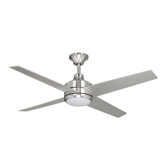
- Page 2 Mercer by Hampton Bay ®...
-
Page 3: Table Of Contents
Thank you for purchasing our ceiling fan. This product has been manufactured with the highest standards of safety and quality. The finish of this fan is weather resistant, but over time will naturally weather and fade. Ceiling Fan by Hampton Bay Date Purchased Table of Contents Store Purchased Safety Rules . -
Page 4: Safety Rules
Safety Rules – Read and Save These Instructions To reduce the risk of electric shock, insure electricity has been turned off at the After making electrical connections, spliced conductors should be turned circuit breaker or fuse box before beginning. upward and pushed carefully up into outlet box. The wires should be spread apart with the grounded conductor and the equipment-grounding conductor All wiring must be in accordance with the National Electrical Code on one side of the outlet box and ungrounded conductor on the other side of... -
Page 5: Unpacking Your Fan
Unpacking Your Fan Unpack your fan and check the contents. You should have the following items: Set of blades (4) Mounting plate Blade attachment hardware (3/16" x 12.3mm screws (13), Canopy assembly (canopy / hanger Light plate 13 fiber washers) bracket / canopy ring / canopy cover) Glass shade Ball/downrod assembly... -
Page 6: Installing Your Fan
Installing Your Fan Provide Strong Support Tools Required Figures 1~3 are examples of different ways to mount the outlet box. Phillips screwdriver, straight slot screwdriver, step ladder and wire cutters. Recessed Ceiling Outlet Box Mounting Plate Mounting Options Figure 3 Outlet Box Note: You may need a longer downrod to If there isn't an existing UL listed mounting box,... -
Page 7: Hanging The Fan
Hanging the Fan Carefully feed motor wires up through the Remove the downrod. Thread the rod into the coupling. Canopy Ring REMEMBER to turn off the power. Follow the Next line up holes and replace cotter pin and steps below to hang your fan properly. clevis pin. -
Page 8: Close-To-Ceiling Mounting
WARNING 6. Slip coupling cover, canopy ring and canopy onto downrod. Carefully reinstall hanger ball FAILURE TO COMPLETELY TIGHTEN THE THREE SCREWS IN STEP 7 COULD RESULT IN onto rod being sure that cross pin is in correct FAN LOOSENING AND POSSIBLY FALLING. position, set screws are tighten and wires are not twisted. -
Page 9: Installing Fan To The Electrical Box
Installing Fan to UL Listed Outlet Box the Electrical Box WARNING 120V Wires TO REDUCE THE RISK OF FIRE, ELECTRIC SHOCK OTHER PERSONAL INJURY. MOUNT FAN ONLY TO AN OUTLET BOX OR SUPPORTING SYSTEM MARKED ACCEPTABLE Groove FOR FAN SUPPORT AND USE THE MOUNTING Ceiling Mounting SCREWS PROVIDED WITH THE OUTLET BOX. - Page 10 Making the Electrical (Fig. Motor receiver electrical connections: Connect the black wire from the Connections fan to black wire marked "TO MOTOR L". Frequency Switch Connect the white wire from the fan to the white wire marked "TO MOTOR N" from the WARNING receiver.
- Page 11 WARNING NOTE SUPPLY CIRCUIT CHECK TO SEE THAT ALL CONNECTIONS ARE FAN MUST BE INSTALLED AT A MAXIMUM TIGHT, INCLUDING GROUND, AND THAT NO DISTANCE OF 40 FEET FROM THE TRANSMIT- BARE WIRE IS VISIBLE AT THE WIRE NUTS. TING UNIT FOR PROPER SIGNAL TRANSMIS- EXCEPT FOR THE GROUND WIRE.
-
Page 12: Standard Ceiling Mounting
Finishing the Fan Close-to-Ceiling Mounting Installation Outlet Box Remove the fan from the tab on the hanger bracket. Secure the canopy to the hanger bracket Standard Ceiling Mounting with four screws included with your fan. (Fig. 20) Hanger Raise up canopy ring and line up the 4 tabs with Screws Bracket WARNING... -
Page 13: Attaching The Fan Blades
Attaching the Fan Blades WARNING TO REDUCE THE RISK OF PERSONAL INJURY, DO NOT BEND THE BLADE HOLDERS WHILE Insert the blade through the blade slot in the Touching Ceiling INSTALLING, BALANCING THE BLADES, OR decorative housing. Align the holes in blade CLEANING THE FAN. -
Page 14: Attaching The Mounting Plate
Attaching the Mounting Plate Remove 1 of 3 screws from the mounting ring and loosen the other 2 screws. (Do not remove) Place the key holes on the mounting plate over the 2 screws previously loosened from the mounting ring, turn mounting plate until it locks in place at the narrow section of the key holes. Secure by tightening the 2 screws previously loosened and the one previously removed. -
Page 15: Installing The Light Kit
Installing the Light Kit CAUTION SHUT OFF THE POWER SUPPLY BEFORE REMOVING OR REPLACING LAMP. IN HANDLING OF HALOGEN BULB, CARE SHOULD BE TAKEN NOT TO TOUCH IT WITH YOUR BARE HANDS. OIL RESIDUE WILL SHORTEN THE LIFE OF THE HALOGEN BULB. IF YOU ACCIDENTALLY COME INTO CONTACT, WIPE THOROUGHLY WITH A CLEAN, LINT-FREE, COTTON CLOTH. -
Page 16: Operating Your Transmitter
Operating Your Transmitter Installing the Battery: Restore power to the ceiling fan and test for proper operation. Install 12V MN21/A23 battery (included), to "HI, MED, LOW" buttons: prevent damage to transmitter, remove the battery These three buttons are used to set the fan if not used for long periods (Figure 25). - Page 17 Installing the Transmitter Speed settings for warm or cool weather depend on factors such as the room size, ceiling height, Holder number of fans, etc. Remove the two plugs from the holder. Note The Reverse switch is located on the top of motor that the plugs have unique tabs that allows housing.
-
Page 18: Care Of Your Fan
Remote control Do not connect the fan with a wall mounted variable speed control(s). Make sure the dip switches are set correctly. THE HAMPTON BAY FAN & LIGHTING CO. WARNING P. O. Box 395 MAKE SURE THE POWER IS OFF AT THE ELECTRICAL PANEL BOX Norco, CA 92860 BEFORE YOU ATTEMPY ANY REPAIRS. -
Page 19: Specifications
Specifications FAN SIZE SPEED VOLTS AMPS WATTS N.W. G.W. C.F. 0.31 1950 6.96 kgs 8.06 kgs 0.43 3418 52" MED. 1.688' (13.35 lbs) (17.73 lbs) 0.54 5119 HIGH These are approximate measures. They do not include Amps and Wattage used by the light kit. Distributed by Home Depot U.S.A., Inc. -
Page 20: Warranty Information
Lifetime Limited Warranty (lifetime warranty on motor) The Hampton Bay warrants the fan motor to be free from defects in workmanship and material present at time You must present a copy of the original purchase receipt to obtain warranty of shipment from the factory for a period of lifetime after the date of purchase by the original purchaser.
Need help?
Do you have a question about the Mercer and is the answer not in the manual?
Questions and answers
How do I get a replacement transmitter for inside the ****?
You can obtain a replacement transmitter for the Hampton Bay Mercer by purchasing a compatible remote control, such as the 53T model. This model is a replacement for Hampton Bay remotes including FAN-53T, FAN-35T, and others. It is sold as a handheld transmitter only and does not include a receiver or battery. Make sure to match the DIP switch settings on the new transmitter to your existing setup for proper operation.
This answer is automatically generated