Table of Contents
Advertisement
Tomcat i915 S5120
User's Manual
///
Tomcat i915
S5120
Revision 1.00
Copyright © TYAN Computer Corporation, 2004. All rights reserved. No part of this manual
may be reproduced or translated without prior written consent from TYAN Computer Corp.
All registered and unregistered trademarks and company names contained in this manual are
property of their respective owners including, but not limited to the following.
TYAN, Tomcat i915 and S5120 are trademarks of TYAN Computer Corporation.
Intel Prescott and combinations thereof are trademarks of Intel Corporation.
Promise is a trademark of Promise Technology, Inc.
Award, AwardBIOS are trademarks of Award Software Incorporated.
Microsoft and Windows are trademarks of Microsoft Corporation.
IBM, PC, AT and PS/2 are trademarks of IBM Corporation.
VIA is a trademark of VIA Technologies, Inc.
Winbond is a trademark of Winbond Electronics Corporation.
SMSC is a trademark of Standard Microsystems Corporation.
Realtek is a trademark of Realtek Semiconductor Corporation.
Broadcom is a trademark of Broadcom Corporation.
Portable Document Format (PDF) is a trademark of Adobe Corporation.
Information contained in this document is furnished by TYAN Computer Corporation and has
been reviewed for accuracy and reliability prior to printing.
TYAN assumes no liability
whatsoever, and disclaims any express or implied warranty, relating to sale and/or use of
TYAN products including liability or warranties relating to fitness for a particular purpose or
merchantability.
TYAN retains the right to make changes to product descriptions and/or
specifications at any time, without notice. In no event will TYAN be held liable for any direct or
indirect, incidental or consequential damage, loss of use, loss of data or other malady resulting
from errors or inaccuracies of information contained in this document.
i
http://www.tyan.com
Advertisement
Table of Contents

Related Manuals for TYAN TOMCAT I915


Summary of Contents for TYAN TOMCAT I915
- Page 1 TYAN retains the right to make changes to product descriptions and/or specifications at any time, without notice. In no event will TYAN be held liable for any direct or indirect, incidental or consequential damage, loss of use, loss of data or other malady resulting from errors or inaccuracies of information contained in this document.
-
Page 2: Table Of Contents
Tomcat i915 S5120 Table of Contents Table of Contents Before you begin… ......................... iv Chapter 1: Introduction......................1-1 1.1 Congratulations!......................1-1 1.2 Hardware Specifications .................... 1-1 Chapter 2: Board Installation ....................2-1 2.1 Installing the Motherboard ..................2-1 2.1.1 Installation Notes ..................... 2-1 2.2 Board Image ...................... - Page 3 Tomcat i915 S5120 Table of Contents 3.5.3 Onboard Device..................... 3-18 3.5.4 Super IO Device..................... 3-20 3.5.5 PCI Express PM Function................3-22 3.5.6 Power On Setup..................... 3-25 3.6 PnP/PCI Configurations ................... 3-27 3.6.1 IRQ Resources ....................3-28 3.7 PC Health Status ..................... 3-29 3.8 Frequency/Voltage Control ..................
-
Page 4: Before You Begin
1 x Ultra-DMA-133/100/66/33 IDE cable (2 for models with Promise SATA RAID) 1 x Tomcat i915 S5120 User’s Manual 1 x Tomcat i915 S5120 Quick Reference Guide 1 x TYAN driver CD 2 x Promise Driver Diskette (only for models with Promise SATA RAID) -
Page 5: Chapter 1: Introduction
Chapter 1: Introduction 1.1 Congratulations! Congratulations on your purchase of the TYAN Tomcat i915 S5120, one of the most powerful and versatile motherboard solutions available for Intel Prescott processors. Based on the acclaimed Intel i915G chipset, the S5120 offers exceptional performance and outstanding features. - Page 6 Form Factor ATX footprint 12” x 9.6” (305mm x 245mm) Regulatory FCC Class B (Declaration of Conformity) CE (Declaration of Conformity) BSMI Note TYAN reserves the right to add support or discontinue support for any OS with or without notice. http://www.tyan.com...
-
Page 7: Chapter 2: Board Installation
TYAN recommends putting on a good quality grounded wrist strap before removing your motherboard from the antistatic bag. -
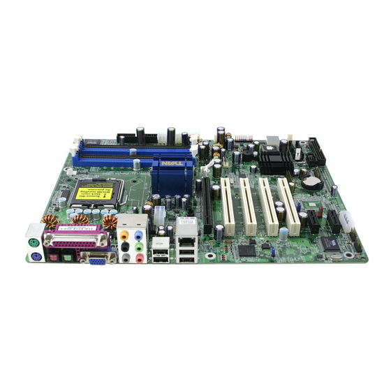
Page 8: Board Image
Chapter 2: Board Installation 2.2 Board Image The following is an image of the Tomcat i915 S5120. The above photograph is purely representative. Due to engineering updates and new board revisions, certain components may change and or be repositioned. The picture above may or may not look exactly like the board you received. -
Page 9: Block Diagram
Tomcat i915 S5120 Chapter 2: Board Installation 2.3 Block Diagram The following is a block diagram of the Tomcat i915 S5120. http://www.tyan.com... -
Page 10: Motherboard Components
Tomcat i915 S5120 Chapter 2: Board Installation 2.4 Motherboard Components The diagram below shows the main motherboard components. (KB+Mouse) KB(Bottom) PFAN SUPER Mouse(Top) (Audio) USB (Bottom) S5120 LAN+ 10/100 LAN (Top) Intel USB1 (Optional) i915G ALC880 LAN+ USB2 x16 PCI Express... -
Page 11: Jumpers And Connectors
Tomcat i915 S5120 Chapter 2: Board Installation 2.5 Jumpers and Connectors Jumpers and connectors are provided on your motherboard for configuration and connection to peripherals. The following section shows you how to set your jumpers and use your connectors. Jumper/ Function Ref. -
Page 12: Serial Port: Com1 (J22)
Tomcat i915 S5120 Chapter 2: Board Installation 2.5.1 Serial port: COM1 (J22) (KB+Mouse) K B(B ottom ) PFAN SUPER Mouse(Top) (Audio) USB (Bottom) S5120 LAN+ 10/100 LAN (Top) Intel USB1 (Optional) i915G ALC880 LAN+ USB2 x16 PCI Express PCI-E1 Pin#... -
Page 13: Cpu Fan Connector: Jp1 (Pfan)
Tomcat i915 S5120 Chapter 2: Board Installation 2.5.3 CPU Fan Connector: JP1 (PFAN) Speed Control (KB+Mouse) K B(B ottom ) +12V PFAN SUPER Mouse(Top) Tachometer V3P3 Use this header to connect the processor cooling fan to your motherboard to keep (Audio) the system stable and reliable. -
Page 14: Raid Ide Connector: Jp4 (Raid-Ide1) (On Sata Raid Model Only)
Tomcat i915 S5120 Chapter 2: Board Installation 2.5.5 RAID IDE Connector: JP4 (RAID-IDE1) (on SATA RAID model only) (KB+Mouse) K B(B ottom ) PFAN SUPER Mouse(Top) Supports RAID 0, 1, 0+1 along with the (Audio) J27 (RAID SATA1) and J28 (RAID SATA2) -
Page 15: Front Panel Audio Connector: Jp8
Tomcat i915 S5120 Chapter 2: Board Installation 2.5.7 Front Panel Audio Connector: JP8 (KB+Mouse) K B(B ottom ) PFAN SUPER M ouse(Top) (Audio) Presence S5120 USB (Bottom) LAN+ 10/100 LAN (Top) Intel AUD FP JS USB1 (Optional) i915G ALC880 LAN+... -
Page 16: Front Panel Usb 2.0 Connectors: Usb3/Usb4 (Jp10/Jp11)
Tomcat i915 S5120 Chapter 2: Board Installation 2.5.9 Front Panel USB 2.0 Connectors: USB3/USB4 (JP10/JP11) (KB+Mouse) KB(B ottom ) PFAN SUPER Mouse(Top) (Audio) USB (Bottom) S5120 LAN+ 10/100 LAN (Top) Intel USB1 (Optional) i915G ALC880 LAN+ USB2 x16 PCI Express... -
Page 17: Gigabit Lan (Bcm5751) Enable/Disable Jumper: Jp18
Tomcat i915 S5120 Chapter 2: Board Installation 2.5.11 Gigabit LAN (BCM5751) Enable/Disable Jumper: JP18 (KB+Mouse) K B(Bottom ) OPEN PFAN SUPER M ouse(Top) CLOSED (Default) (Audio) USB (Bottom) S5120 LAN+ 10/100 LAN (Top) Intel USB1 (Optional) i915G ALC880 Disable the on board Gigabit LAN function... -
Page 18: Chassis Fan Connector: Jp20 (Fan3)
Tomcat i915 S5120 Chapter 2: Board Installation 2.5.13 Chassis Fan Connector: JP20 (FAN3) (KB+Mouse) K B(B ottom ) PFAN SUPER Mouse(Top) Tachometer +12V Use this header to connect the chassis (Audio) cooling fans to your motherboard to keep USB (Bottom) -
Page 19: 10/100 Lan (Intel 82551Qm) Enable/Disable Jumper: Jp23 (Optional)
Some chassis’ include plastic studs instead of metal. Although the plastic studs are usable, TYAN recommends using metal studs with screws that will fasten the motherboard more securely in place. -
Page 20: Installing Memory
Before installing memory, ensure that the memory you have is compatible with the motherboard and processor. PC2700/PC3200 (DDR333/DDR400) modules are required. Check the TYAN Web site at: www.tyan.com for details of the type of memory recommended for your motherboard. The following diagram shows common types of memory modules. -
Page 21: Memory Installation Procedure
Seat the module firmly into the socket by gently pressing down until it sits flush with the socket. The locking levers pop up into place. 2.8 Installing the Processor and Cooling Fan Your Tomcat i915 S5120 supports the latest processor technologies from Intel. Check the TYAN website for latest processor support: http://www.tyan.com 2-15 http://www.tyan.com... - Page 22 Tomcat i915 S5120 Chapter 2: Board Installation Processor Installation The processor should be installed carefully. Make sure you are wearing an antistatic strap and handle the processor as little as possible. Follow these instructions to install your processor Locate the processor socket on the motherboard and lift the protective cover off as shown.
- Page 23 Tomcat i915 S5120 Chapter 2: Board Installation Cooling Fan Installation After you have installed the processor, the heatsink should be installed to ensure that the processor runs efficiently and does not overheat. Use the heatsink supplied for best results. Follow these instructions to install the heatsink shown.
-
Page 24: Installing Drive Cables
2.9 Installing Drive Cables IDE and FDD connectors are “keyed” to only allow insertion only one way. TYAN motherboards have two on-board IDE channels, each supporting two drives. The black connector is a standard IDE channel. Only the blue connector supports RAID. -
Page 25: Installing Expansion Cards
Tomcat i915 S5120 Chapter 2: Board Installation Troubleshooting Floppy Drives See the chart below for troubleshooting floppy disk drive installations. Symptoms of incorrectly installed floppy drives Usually caused by faulty cables, cables put in backwards or a faulty floppy drive. Try another floppy drive or try replacing the cable. -
Page 26: Connecting External Devices
Tomcat i915 S5120 Chapter 2: Board Installation 2.11 Connecting External Devices Your new motherboard supports a number of different interfaces for connecting peripherals. See the diagram below. Port definitions: PS2 mouse port (green) PS2 keyboard port (purple) SPDIF-IN port (red) -
Page 27: Installing The Power Supply
2.12 Installing the Power Supply There are three power connectors on your Tomcat i915 S5120. By default, the Tomcat i915 S5120 requires that you have an EPS12V power supply that has a 24-pin and an 8-pin power connector. However, the Tomcat i915 S5120 is also ATX12V compatible. All 3 power connectors need to be used if you plan on using the ATX12V power. -
Page 28: Chapter 3: Bios Setup
Tomcat i915 S5120 Chapter 3: BIOS Setup Chapter 3: BIOS Setup 3.1 About the BIOS The BIOS is the basic input/output system, the firmware on the motherboard that enables your hardware to interface with your software. This chapter describes different settings for the BIOS that can be used to configure your system. -
Page 29: In Case Of Problems
Only alter settings that you thoroughly understand. In particular, do not change settings in the Chipset section unless you are sure of the outcome. TYAN or your system manufacturer has carefully chosen the chipset defaults for best performance and reliability. Even a small change to the Chipset setup options may cause the system to become unstable or unusable. - Page 30 Tomcat i915 S5120 Chapter 3: BIOS Setup Integrated Peripherals Use this menu to specify your settings for integrated peripherals. Power Management Setup Use this menu to specify your settings for power management. PnP / PCI Configuration This entry appears if your system supports PnP / PCI.
-
Page 31: Standard Cmos Features
Tomcat i915 S5120 Chapter 3: BIOS Setup 3.3 Standard CMOS Features In this section, you can alter general features such as the date and time, as well as access to the IDE configuration options. Note that the options listed below are for options that can directly be changed within the Main Setup screen. -
Page 32: Advanced Bios Features
Tomcat i915 S5120 Chapter 3: BIOS Setup Halt On Determines if the computer should stop when an error is detected during power up. • No Errors • All Errors • All, But Keyboard • All, But Diskette • All, But Disk/Key 3.4 Advanced BIOS Features... - Page 33 Tomcat i915 S5120 Chapter 3: BIOS Setup of the total number of clock cycles. This results in the processor "resting" for 50-70% of the time. As the die temperature drops, the TCC will gradually reduce the number of null cycles until no more is required to keep the die temperature below the safe point.
- Page 34 Tomcat i915 S5120 Chapter 3: BIOS Setup CPU L1 & L2 Cache This option toggles the use of CPU L1 and L2 cache. The L1 cache is also called the primary cache or internal cache and is built into the processor. The L2 cache also called as the external cache is placed between the CPU and the DRAM (dynamic RAM).
-
Page 35: Boot Sequence
Tomcat i915 S5120 Chapter 3: BIOS Setup Select the MPS version depending on the operating system installed: select 1.1 for Win NT 3.52, and 1.4 for Win NT4.0, Win2000, and WinXP. • • Note This option cannot be changed if APIC Mode is set to Disabled. - Page 36 Tomcat i915 S5120 Chapter 3: BIOS Setup The removable boot device priority is as follows. Internal Floppy Disks LS120 Disk Internal Zip Disk USB Floppy Disk USB Floppy Disk USB ZIP Disk USB ZIP Disk Hard Disk Boot Priority This setting controls the order that the BIOS uses to look for a hard disk from which to load the operating system during the boot process.
- Page 37 Tomcat i915 S5120 Chapter 3: BIOS Setup Boot Up Floppy Seek During Power-On Self-Test (POST), BIOS will determine if the floppy disk drive installed is 40 or 80 tracks. • Enabled • Disabled Boot Up NumLock Status This option, when enabled, automatically turns on your NumLock key when the system is booted.
-
Page 38: Advanced Chipsets Features
Tomcat i915 S5120 Chapter 3: BIOS Setup Security Option Setting this option to System will set the BIOS to ask for the password each time the system boots up. If you choose Setup, then the password is only required for access into the BIOS setup menus. - Page 39 Tomcat i915 S5120 Chapter 3: BIOS Setup DRAM Timing Selectable This option permits you to either manually select memory timings, or allow the SPD (Serial Presence Detect) to determine the said timings automatically. • Manual • By SPD Note On all memory timing settings, lower number is more aggressive.
-
Page 40: Pci Express Root Port Func
Tomcat i915 S5120 Chapter 3: BIOS Setup System Memory Frequency Changing this option allows the memory to be run asynchronously from the FSB but it is best if it is left at AUTO. • Auto • DDR333 • DDR400 System BIOS Cacheable Enabling this option will cause the BIOS code from ROM to be copied on to the much faster RAM at location F0000h-FFFFFh, thus increasing system performance. - Page 41 Tomcat i915 S5120 Chapter 3: BIOS Setup PCI Express on the other hand implements a serial, point-to-point type interconnect for communication between two devices. Multiple PCI Express devices are interconnected via the use of switches, which means one can practically connect a large number of devices together in a system.
- Page 42 Tomcat i915 S5120 Chapter 3: BIOS Setup On-Chip Frame Buffer Size This determines the amount of system memory to allocate to video memory. This corresponds to the amount of memory on the onboard graphics card. • • • • 16MB •...
-
Page 43: Onchip Ide Device
Tomcat i915 S5120 Chapter 3: BIOS Setup 3.5.2 OnChip IDE Device IDE HDD Block Mode The IDE HDD Block Mode feature speeds up hard disk access by transferring data from multiple sectors at once instead of using the old single sector transfer mode. When you enable it, the BIOS will automatically detect if your hard disk supports block transfers and configure the proper block transfer settings for it. - Page 44 Tomcat i915 S5120 Chapter 3: BIOS Setup Primary / Secondary Master / Slave PIO The four IDE PIO (Programmed Input / Output) fields let you set a PIO mode (0-4) for each of the four IDE devices that the onboard IDE interface supports. Modes 0 through 4 provide successively increased performance.
-
Page 45: Onboard Device
Tomcat i915 S5120 Chapter 3: BIOS Setup 3.5.3 Onboard Device USB Controller This option enables or disables IRQ allocation for the USB (Universal Serial Bus) controller. Enable this if you are using a USB device. If you disable this while using a USB device, you may have problems running that device. - Page 46 Tomcat i915 S5120 Chapter 3: BIOS Setup USB Mouse Support Set this option to enabled if your system has a USB controller (including USB 2.0) and a USB mouse. • Disabled • Enabled Onboard Audio This enables/disables the on board Azalia sound chip. The default is Auto, which automatically determines whether to enable or disable this chip.
-
Page 47: Super Io Device
Tomcat i915 S5120 Chapter 3: BIOS Setup 3.5.4 Super IO Device Onboard FDC Controller Select Enabled if your system has a floppy disk controller (FDC) installed on the system board and you wish to use it. If you install an add-in FDC or the system has no floppy drive, select “Disabled”... - Page 48 Tomcat i915 S5120 Chapter 3: BIOS Setup Generally, because of its FIFOs and the DMA channel it uses, ECP is good for large data transfers (useful for scanners and printers). On the other hand, EPP is better with links that switch directions frequently (like parallel port drives).
-
Page 49: Pci Express Pm Function
Tomcat i915 S5120 Chapter 3: BIOS Setup Power Management Setup Options related to power management can be altered through the following: 3.5.5 PCI Express PM Function PCI Express components are permitted to wakeup the system using a wakeup mechanism followed by a power management event (PME) Message. PCI Express systems may provide the optional auxiliary power supply (Vaux) needed for wakeup operation from states where the main power supplies are off. - Page 50 Tomcat i915 S5120 Chapter 3: BIOS Setup ACPI allows the Operating System (instead of the BIOS) to control Power Management (OSPM). The ACPI Standard defines hardware registers (which are implemented in chipset silicon), BIOS interfaces, which include configuration tables, control methods, and motherboard device enumeration and configuration;...
- Page 51 Tomcat i915 S5120 Chapter 3: BIOS Setup Video Off Method This option defines the method used to power off video. The various methods are as follows. • Blank Screen: The system BIOS will only send a blank screen when disabling video.
-
Page 52: Power On Setup
Tomcat i915 S5120 Chapter 3: BIOS Setup Intruder# Detection When enabled, this option prevents chassis intrusion. Once you open the system casing, the system marks the chassis as open. Even if you close the casing again, the system still records the chassis as open. Only the system manufacturer can reset this. - Page 53 Tomcat i915 S5120 Chapter 3: BIOS Setup USB KB Wake-Up From S3 If you have a USB keyboard, then you must enable this function to wake-up the system with a key press. • Enabled • Disabled Note This option is enabled only if S3 or S1 & S3 is selected from the ACPI Suspend Type option.
-
Page 54: Pnp/Pci Configurations
Tomcat i915 S5120 Chapter 3: BIOS Setup 3.6 PnP/PCI Configurations This section allows configuring PnP / PCI resources. Init Display First This BIOS feature allows you to select whether to boot the system using the PCI Express graphics card or the PCI graphics card. This is particularly important if you have PCI Express and PCI graphics cards but only one monitor. -
Page 55: Irq Resources
Tomcat i915 S5120 Chapter 3: BIOS Setup Resources Controlled By When this option is set to AUTO, the BIOS by using ESCD, controls the IRQ and DMA assignments of all of the boot and PNP devices in the system. If you set this option to Manual, you will be able to manually assign all IRQ and DMA information. -
Page 56: Pc Health Status
Tomcat i915 S5120 Chapter 3: BIOS Setup INT Pin (1,2,3,4,5,6,7,8) Assignment This setting defines the IRQ for the PCI devices. • Auto • • • • • • • Maximum Payload Size This setting defines the maximum payload size. •... -
Page 57: Frequency/Voltage Control
The CPU clock ratio setting defines how fast the CPU clock runs relative to the bus speed. TYAN does not recommend changing this setting from the default setting. Enter any integer value between 8 and 50. The default is 8x. - Page 58 Tomcat i915 S5120 Chapter 3: BIOS Setup Spread Spectrum This BIOS feature allows you to reduce the EMI of your motherboard by modulating the signals it generates so that the spikes are reduced to flatter curves. It achieves this by varying the frequency slightly so that the signal does not use any particular frequency for more than a moment.
-
Page 59: Load Fail-Safe Defaults
Tomcat i915 S5120 Chapter 3: BIOS Setup DRAM Voltage Regulator This option controls how much voltage is supplied to your DRAM, with a maximum allowable voltage adding of 200mV. Select Default if you are not sure. • Default • +50mV •... -
Page 60: Load Optimized Defaults
Tomcat i915 S5120 Chapter 3: BIOS Setup 3.10 Load Optimized Defaults When you press <Enter> on this item you get a confirmation dialog box with a message similar Load Optimized Defaults (Y/N)? N Pressing ‘Y’ loads the default values that are factory settings for optimal system performance operations. -
Page 61: Enter Password
Tomcat i915 S5120 Chapter 3: BIOS Setup 3.12 Enter Password Type the password, up to eight characters in length, and press <Enter>. The password typed now will clear any previously entered password from CMOS memory. You will be asked to confirm the password. -
Page 62: Exit Selecting
Tomcat i915 S5120 Chapter 3: BIOS Setup 3.13 Exit Selecting Save & Exit Setup Pressing <Enter> on this item asks for confirmation: Save to CMOS and EXIT (Y/N)? Y Pressing “Y” stores the selections made in the menus in CMOS – a special section of memory that stays on after you turn your system off. -
Page 63: Chapter 4: Sata/Raid Setup (For Sata Raid Model)
Tomcat i915 S5120 Chapter 4: SATA/RAID Setup (for SATA RAID model) Chapter 4: SATA/RAID Setup (for SATA RAID model) ® The motherboard includes the Promise PDC20579 SATA RAID controller with two Serial ATA interfaces and one Parallel ATA133 interface to support RAID 0, 1, 0+1 or Ultra ATA configuration Note: The interfaces that PDC20579 support only connect HDDs. -
Page 64: Create Your Disk Array
Tomcat i915 S5120 Chapter 4: SATA/RAID Setup (for SATA RAID model) 4.2 Create Your Disk Array You will now use the onboard FastBuild™ BIOS utility to create your array using the attached drives. See page 23 for a full discussion of the FastBuild utility. -
Page 65: Creating A Security Array With New Drives
Tomcat i915 S5120 Chapter 4: SATA/RAID Setup (for SATA RAID model) 3. Exit the FastBuild Utility. 4. Once the array has been created, you must partition and format the array, using your operating system, as if it were a new single disk drive. - Page 66 Tomcat i915 S5120 Chapter 4: SATA/RAID Setup (for SATA RAID model) Follow these steps: 1. Press the Spacebar to choose Security in the Optimize Array field. 2. Press Ctrl-Y to Save your selection. The window below will appear. 3. Press Y for the Create and Duplicate option. The window below will appear asking you to select the Source drive to use.
-
Page 67: Security Array With Quick Initialization
Tomcat i915 S5120 Chapter 4: SATA/RAID Setup (for SATA RAID model) 4.2.4 Security Array with Quick Initialization Use this setting to create a Mirrored (RAID 1) array with one or two existing disk drives containing data that you do not want to keep. This method creates a mirrored array and erases the first data block from your existing drives. -
Page 68: Install Software Drivers
Tomcat i915 S5120 Chapter 4: SATA/RAID Setup (for SATA RAID model) 4.3 Install Software Drivers Following are driver installation procedures for the Windows operating systems that support the FastTrak 579 Serial ATA RAID controller. Important If you wish to include your current bootable drive using the Windows... -
Page 69: Windows Xp
Tomcat i915 S5120 Chapter 4: SATA/RAID Setup (for SATA RAID model) 4.3.2 Windows XP New Installation The following details the installation the FastTrak Serial ATA RAID Controller drivers while installing Windows XP. 1. Start the installation: • Floppy Install: Boot the computer with the Windows XP installation diskettes. -
Page 70: Windows 2000
Tomcat i915 S5120 Chapter 4: SATA/RAID Setup (for SATA RAID model) 4.3.3 Windows 2000 New Installation The following details the installation of the FastTrak Serial ATA RAID Controller drivers while installing Windows 2000. 1. Start the installation: • Floppy Install: Boot the computer with the Windows 2000 installation diskettes. -
Page 71: Install Pam Software
Tomcat i915 S5120 Chapter 4: SATA/RAID Setup (for SATA RAID model) 4.4 Install PAM Software Follow these steps to install PAM on each computer: 1. Boot the computer and launch Windows. 2. If the computer is already running, exit all programs. - Page 72 Tomcat i915 S5120 Chapter 4: SATA/RAID Setup (for SATA RAID model) 9. In the Setup Type dialog box, make your choice between Complete (Recommended) and Custom installation. Use the Custom installation to change install locations or to deselect individual components.
-
Page 73: Launch Pam And Log-In
Tomcat i915 S5120 Chapter 4: SATA/RAID Setup (for SATA RAID model) 4.4.1 Launch PAM and Log-in To start PAM: 1. Click on a Desktop icon or go to Start > Programs > Promise Array Management and select Local PAM. When the PAM user interface appears: Right-click on the RAID Machine icon in Tree View. -
Page 74: Fastbuild™ Configuration Utility
Tomcat i915 S5120 Chapter 4: SATA/RAID Setup (for SATA RAID model) 4.5 FastBuild™ Configuration Utility • View the FastTrak BIOS Screen • Navigate the FastBuild Menus • Create Arrays Automatically • View Drive Assignments • Create Arrays Manually • Delete an Array •... -
Page 75: Navigate The Fastbuild Menus
Tomcat i915 S5120 Chapter 4: SATA/RAID Setup (for SATA RAID model) 4.5.2 Navigate the FastBuild Menus When using the menus, these are some of the basic navigation tips: Arrow keys highlights through choices; the Space bar allows to cycle through options; Enter selects an option; Esc aborts or exits the current menu. -
Page 76: View Drive Assignments
Tomcat i915 S5120 Chapter 4: SATA/RAID Setup (for SATA RAID model) Performance RAID 0 (Stripe) supports higher read/write performance. The storage capacity equals the number of drives times the capacity of the smallest drive in the disk array. Under the Performance setting, FastTrak assigns two drives to a single Striped array. -
Page 77: Create Arrays Manually
Tomcat i915 S5120 Chapter 4: SATA/RAID Setup (for SATA RAID model) 4.5.5 Create Arrays Manually The Define Array (3) option from the Main Menu allows users to begin the process of manually defining the drive elements and RAID levels for one or multiple disk arrays attached to FastTrak controller. - Page 78 Tomcat i915 S5120 Chapter 4: SATA/RAID Setup (for SATA RAID model) Stripe Block Size For striped (RAID 0) arrays you can manually select the stripe block size. Press the Spacebar to scroll through choices progressing as follows (32, 64, 128 MB).
- Page 79 Tomcat i915 S5120 Chapter 4: SATA/RAID Setup (for SATA RAID model) 5. Press Ctrl-Y to save the information. The window below will appear. 6. Press N for the Create Only option. When the array is created, the screen will return to the Define Array menu.
- Page 80 Tomcat i915 S5120 Chapter 4: SATA/RAID Setup (for SATA RAID model) 7. Press the arrow keys to highlight the drive with the existing data to be copied. This is the Source drive. Warning All Target drive data will be erased. Make sure you choose the correct Source drive.
-
Page 81: Delete An Array
Tomcat i915 S5120 Chapter 4: SATA/RAID Setup (for SATA RAID model) How FastTrak Saves Array Information All disk array data is saved into the reserved sector on each array member. Promise suggests that users record their disk array information for future reference. -
Page 82: Rebuild A Mirrored Array
Tomcat i915 S5120 Chapter 4: SATA/RAID Setup (for SATA RAID model) The boot sector maps the data partition on the disk drive. To delete an array without deleting the data, press N. This action is sometimes part of a data recovery operation, under the direction of Technical Support. - Page 83 Tomcat i915 S5120 Chapter 4: SATA/RAID Setup (for SATA RAID model) 6. Power off your system. 7. Remove the failed drive and replace it with a new drive of the same or larger size. 8. Power on your system and enter the FastBuild Utility.
-
Page 84: Chapter 5: Diagnostics
The most common type of error is a memory error. Before contacting your vendor or TYAN Technical Support, be sure that you note as much as you can about the beep code length and order that you experience. Also, be ready with information regarding add-in cards, drives and O/S to speed the support process and come to a quicker solution. -
Page 85: Appendix I: Glossary
Tomcat i915 S5120 Appendix I: Glossary Appendix I: Glossary ACPI (Advanced Configuration and Power Interface): a power management specification that allows the operating system to control the amount of power distributed to the computer’s devices. Devices not in use can be turned off, reducing unnecessary power expenditure. - Page 86 EEPROM (Electrically Erasable Programmable ROM): also called Flash BIOS, is a ROM chip which can, unlike normal ROM, be updated. This allows you to keep up with changes in the BIOS programs without having to buy a new chip. TYAN’s BIOS updates can be found at http://www.tyan.com...
- Page 87 Form factor: an industry term for the size, shape, power supply type, and external connector type of the Personal Computer Board (PCB) or motherboard. The standard form factors are the AT and ATX, although TYAN also makes some Baby-AT and ATX Footprint boards. Global timer: onboard hardware timer, such as the Real-Time Clock (RTC).
- Page 88 Tomcat i915 S5120 Appendix I: Glossary Latency: the amount of time that one part of a system spends waiting for another part to catch up. This is most common when the system sends data out to a peripheral device, and it waiting for the peripheral to send some data back (peripherals tend to be slower than onboard system components).
- Page 89 Tomcat i915 S5120 Appendix I: Glossary RAID (Redundant Array of Independent Disks): a way for the same data to be stored in different places on many hard drives. By using this method, the data is stored redundantly, also the multiple hard drives will appear as a single drive to the operating system. RAID level 0 is known as striping, where data is striped (or overlapped) across multiple hard drives, but offers no fault-tolerance.
- Page 90 Tomcat i915 S5120 Appendix I: Glossary SSI (Server System Infrastructure): an industry initiative intended to provide ready-to-use design specifications for common server hardware elements (chassis, power supplies, and racks) to promote and support server industry growth. Standby mode: in this mode, the video and hard drives shut down; all other devices continue to operate normally.
-
Page 91: Appendix Ii: Post Error Code For Bios
Tomcat i915 S5120 Appendix II: Post Error Code for BIOS Appendix II: Post Error Code for BIOS POST (hex) Description Test CMOS R/W functionality. CFh: Early chipset initialization: C0h: -Disable shadow RAM -Disable L2 cache (socket 7 or below) -Program basic chipset registers... - Page 92 Tomcat i915 S5120 Appendix II: Post Error Code for BIOS POST (hex) Description Detect CPU information including brand, SMI type (Cyrix or Intel) and 18h: CPU level (586 or 686). Initial interrupts vector table. If no special specified, all H/W interrupts are 1Bh: directed to SPURIOUS_INT_HDLR &...
- Page 93 Tomcat i915 S5120 Appendix II: Post Error Code for BIOS POST (hex) Description Test DMA Channel 1. 37h: Test DMA page registers. 39h: Test 8254 3Ch: Test 8259 interrupt mask bits for channel 1. 3Eh: Test 8259 interrupt mask bits for channel 2.
- Page 94 Tomcat i915 S5120 Appendix II: Post Error Code for BIOS POST (hex) Description Prepare memory size information for function call: INT 15h ax=E820h 67h: Turn on L2 cache 69h: Program chipset registers according to items described in Setup & Auto- 6Bh: configuration table.
- Page 95 Tomcat i915 S5120 Appendix II: Post Error Code for BIOS POST (hex) Description 1. Call chipset power management hook. 82h: 2. Recover the text fond used by EPA logo (not for full screen logo) 3. If password is set, ask for password.
-
Page 96: Technical Support
Return Merchandise Authorization (RMA) number. The RMA number should be prominently displayed on the outside of the shipping carton and the package should be mailed prepaid. TYAN will pay to have the board shipped back to you. 6-12 http://www.tyan.com... - Page 97 Tomcat i915 S5120 User’s Manual Notice for the USA Compliance Information Statement (Declaration Conformity Procedure) DoC FCC Part 15: This device complies with part 15 of the FCC Rules Operation is subject to the following conditions: This device may not cause harmful interference, and This device must accept any interference received including interference that may cause undesired operation.
Need help?
Do you have a question about the TOMCAT I915 and is the answer not in the manual?
Questions and answers