Table of Contents
Advertisement
Quick Links
LPRT 518049
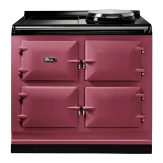
AGA eR7i
Model No's: eR7i 100-3 and eR7i 150-5
Installation Guide
WARNING!
Please read the Warning, Cautionary notes at the start of this section.
If the information contained within these instructions is not followed,
property damage or personal injury may occur.
DO NOT store or use gasoline or other flammable vapors and liquids in the
vicinity of this or any other appliance.
Installation and service must be performed by a qualified installer or service
agency.
WARNING! This appliance must be installed with an appropriate device that
will allow permanent disconnection of the Live and Neutral conductors. During
Installation or disconnection prior to any electrical work, the appliance must be
permanently disconnected from the Supply (Live) and Neutral Conductors.
CAUTION: THIS UNIT IS HEAVY, PROPER EQUIPMENT AND ADEQUATE MANPOWER MUST BE USED IN MOVING THE
RANGE TO AVOID DAMAGE TO THE UNIT OR THE FLOOR.
REMEMBER, when replacing a part on this appliance, use only spare parts that you can be assured conform to the safety and
performance specification that we require.
DO NOT use reconditioned or copy parts that have not been clearly authorised by AGA.
PLEASE READ THESE INSTRUCTIONS BEFORE USING THIS APPLIANCE
AND KEEP IN A SAFE PLACE FOR FUTURE REFERENCE.
For use in GB and IE
07/24 EINS 518050
Advertisement
Table of Contents

Related Manuals for AGA eR7i 150-5


Summarization of Contents
Health and Safety
Consumer Protection
Manufacturer's commitment to safety standards and user guidance.
Cooker Base or Hearth Requirements
Ensuring the base is level and can support the cooker's total weight.
Tiling Guidelines
Recommendations for tiling around the cooker for servicing access.
Handling Hazardous Materials
Precautions for materials like mineral wool and ceramic fibre, recommending PPE.
General Cooking Safety
Advice on fire prevention, handling hot pans, and deep fat frying procedures.
Installation Requirements
Installer Qualification and Compliance
Mandatory installation by trained engineers, adhering to regulations.
Delivery and Access Requirements
Information on appliance delivery, access needs, and manoeuvring space.
AGA eR7i 100-3 Dimensions
Detailed measurements and diagrams for the AGA eR7i 100-3 model.
AGA eR7i 150-5 Dimensions
Detailed measurements and diagrams for the AGA eR7i 150-5 model.
Clearances for Installation
Minimum gaps for side, door access, service, and tiling around the appliance.
Power Supply - AGA eR7i
Electrical Requirements
Details on required voltage, amperage, cable size, and isolation for the AGA eR7i.
Induction Hob Power Supply
Specific power supply needs for the induction hob attachment.
Hotcupboard Power Supply
Independent power supply requirements for the hotcupboard attachment.
Mains Cable Routing - AGA eR7i
Cable Routing Diagram
Illustrates permitted zones and cable exit points for the AGA eR7i.
Connection Point Zones
Defines the areas where the mains supply connection point must be located.
Mains Cable Routing - AGA Hotcupboard
Hotcupboard Cable Routing
Diagram showing cable exit and permitted connection zones for the hotcupboard.
Connection Point Restrictions
Specifies zones for connection points, avoiding positions above or behind the appliance.
Hotcupboard Installation
Initial Positioning and Top Plate Adjustment
Procedure for detaching, sliding, and adjusting the hotcupboard top plate.
Plinth Alignment and Leveling
Ensuring plinths are level and correctly aligned with the AGA eR7i.
Securing Plinths Together
Methods for attaching and locking the hotcupboard plinth to the AGA eR7i plinth.
Handrail and Plinth Facia Fitting
Steps for assembling the handrail and fitting the plinth facias.
Final Checks and Commissioning
Locking handrails, fitting facias, and performing functional tests.
Circuit Diagram
AGA Hotcupboard Circuit Diagram
Electrical schematic for the AGA Hotcupboard, including component identification.
Wiring Cautionary Notes
Important warnings regarding labeling wires and verifying operation after servicing.
AGA eR7i Wiring Diagram
Detailed wiring diagram for the AGA eR7i, showing component connections.
Component Identification
Labeling of electrical components and connection points within the wiring diagram.
Need help?
Do you have a question about the eR7i 150-5 and is the answer not in the manual?
Questions and answers