Table of Contents
Advertisement
Quick Links
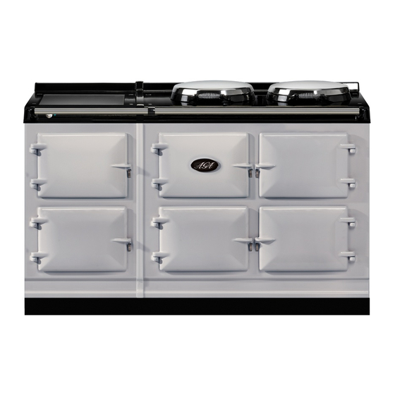
TC/DC INTEGRATED MODULE (FFD)
WARNING: If the information in this manual is not followed exactly, a fire or
explosion may result causing property damage,personal injury or death.
Do not store or use gasoline or other flammable vapors and liquids in the vicinity
of this or any other appliance.
WHAT DO YOU DO IF YOU SMELL GAS
.
Do not try to light any appliance.
.
Do not touch any electrical switch
.
Do not use any phone in your building.
.
Immediately call your gas supplier from a neighbors phone.
Follow the gas suppliers instructions
.
If you can not reach your gas supplier call the fire department.
Installation and service must be performed by a qualified installer, service agency
or the gas supplier.
PLEASE READ THESE INSTRUCTIONS BEFORE COMMENCING INSTALLING THIS APPLIANCE.
IMPORTANT :
IMPORTANT :
(with Gas Top Burners)
Installation
SAVE INSTRUCTIONS FOR FUTURE REFERENCE
CONSERVER CES INSTRUCTIONS POUR REFERENCE FUTURE
For use in USA/Canada
uide
06/15 EINS 517026
Advertisement
Table of Contents


Need help?
Do you have a question about the TC Series and is the answer not in the manual?
Questions and answers