
Related Manuals for FISCHER ISOSCOPE DMP10


Summary of Contents for FISCHER ISOSCOPE DMP10
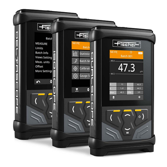
- Page 1 Operator’s Manual Gauges for coating thickness measurement DELTASCOPE® DMP10 ISOSCOPE® DMP10 DUALSCOPE® DMP20...
- Page 2 Industriestraße 21 www.helmut-fischer.com D-71069 Sindelfingen mail@helmut-fischer.com On our home page www.helmut-fischer.com you will find the addresses of our sole agencies and subsidiary companies around the globe. Quality Assurance System of the Helmut Fischer GmbH Institut für Elektronik und Messtechnik DIN EN ISO/IEC 17025 Calibration lab accredited for certified mass per unit...
-
Page 3: Table Of Contents
..........Safety Warnings and icons used . - Page 4 ......... . Measure Notes on measuring .
- Page 5 ........13 Gauge settings 13.1 Setting the language .
- Page 6 DMP10 / DMP20...
-
Page 7: Safety
Safety ► Refer to the safety information before starting-up this gauge in order to avoid damage to property or personal injury. ► Keep this manual in a safe place to be able to refer to any necessary descrip- tions at a later date. Warnings and icons used ATTENTION Indicates a danger that can lead to damage or destruction of the product. -
Page 8: Intended Use
Intended use The gauge is intended solely for the measurement of coating thicknesses. The measurement system (gauge and probe) is designed for operation under the fol- lowing environmental conditions: Indoor and outdoor operation Operation outside potentially explosive areas only! ... - Page 9 ATTENTION – Damage due to high temperature When exposed to sunshine, the areas behind glass windows (e.g. in a car) can easily reach temperatures in excess of +50 °C (+122 °F). This can cause damage to the gauge. Do not keep or store the gauge and accessories behind glass panes, or near to heat sources such as radiators etc.! ATTENTION –...
-
Page 10: Maintenance And Repairs
► Do not continue to use the battery if you notice any changes such as discoloration, deformation or damage to the outer casing. ► Replace the battery if it is not charged after the usual charging time. The usual charging time can be found in the technical data. -
Page 11: Limitation Of Liability
Limitation of liability The manufacturer accepts no liability and no responsibility for the precision, conclu- sions, and interpretation of the measurement results. Only continuous monitoring of the measurement devices by the user can guarantee the continued precision of mea- surements. The manufacturer accepts no liability or responsibility for consequential damage caused by the use of incorrect measured readings. -
Page 12: Scope Of Supply
Scope of supply Gauge Li-ion battery USB cable type C to type A, 1 m (39.4 ") Safety information and quick guide Gauge case Gauge Battery compartment lid Light strip for displaying the mea- sured reading acquisition, specifica- tion limit violation, battery charge status Display... -
Page 13: Overview Of Signals
Setting values faster • Measure once on the surface. You can use this value to set the desired value faster. • Press and hold the arrow keys longer. Overview of signals If all signal functions in the gauge are activated, the gauge reports the following states: Beeps Short beep = measured reading acquisition complete, second beep in addition... - Page 14 Moves the cursor using the arrow keys • Moves the selection marking • Increases/decreases the numerical value displayed Calls up the Delete function Opens another menu page Scrolls, displays the next page • Confirm the message/information • Starts the function (e.g. Delete function) Cancels the setting process and exits the function or returns to the previous page without saving any changes Confirm...
-
Page 15: Measurement View
Measurement view NF/FE Currently measured coating/base Batch 001 material combination, NF/FE or NC/ 47.3 49.0 Batch name µm Specification limits 44.5 Reading currently being measured 46.8 Statistical values 1.81 44.9 Key assignment line (example: delete 48.5 V[%] function, calibration function) Status displays;... - Page 16 NF/FE Displays the currently measured coating/base material combination: non-fer- rous coating material on ferrous base material; display only with the DELTA- SCOPE® and DUALSCOPE® gauge models NC/NF Displays the currently measured coating/base material combination: electri- cally non-conductive and non-ferrous coating material on electrically conduc- tive non-ferrous metals;...
-
Page 17: Menus - Function Overview
Standard deviation for the arithmetic mean ; a measure for the variation of individual measured readings around their common mean value. Lowest measured reading in the batch Highest measured reading in the batch The range equals the difference between the highest and lowest measured reading in a batch V[%] Coefficient of variation, percentage variation of a series of measurements,... - Page 18 Batch Modify > Views Settings • Measurement view: selects the display • Batch statistical display: selects the statistical characteristic variables to be displayed Batch Modify > Meas. unit Sets the unit of measurement Batch Modify > Offset Sets the offset value Batch Modify >...
- Page 19 • Shortened course Activates a semi-automatic calibration routine • Reset Deletes all coating thickness correction values from the selected calibration • Delete Deletes the selected calibration from the probe memory • Info Displays information about the selected calibration Gauge Settings menu >...
-
Page 20: Statistical Characteristic Variables
• Delete all calibrations Deletes all calibrations from the memory of the connected probe; NOTE: You cannot measure without a calibration! Gauge Settings > About Information about the firmware version, copyright and connected probe Statistical characteristic variables – Mean Value Arithmetic mean value ( ) of all measured readings. -
Page 21: Technical Data
Description With these gauge models you measure coating thicknesses easily, quickly, non- destructively and with the precision that is typical for all Fischer instruments. This gauge family contains gauges for measurement on ferrous, electrically con- ductive base material, or both base material models. - Page 22 Applications Examples DELTASCOPE ISOSCOPE DUALSCOPE DMP10 DMP10 DMP20 Base material steel or iron (FE) Zn, Cr, Cu coating on steel or iron (NF/FE) Paint, varnish, plastic coating on steel or iron (NC/FE) Base material electrically conductive (NF) Base material electrically conductive (NF) Paint, varnish, plastic coating on Paint, varnish, plastic coating on...
- Page 23 Limit Monitoring Can be disabled; limit values can be set Offset value/ correction value Can be set, is deducted automatically from the measured reading. Thus, one ob- tains the thickness of the top coating if for instance the interim coating is known. Resolution of the displayed values Low (up to 1 decimal place) ...
- Page 24 probe identifiable by the USB-C female jack and by the probe name, always be- ginning with the letter D Analog probe: connection via DMP-F-probe-Adapter plugged into the gauge; a total of up to 100 calibrations can be stored in the DMP-F-Probe-Adapter; only the calibrations that were created with the probe connected to the DMP-F- Probe-Adapter are available in the gauge in each case.
- Page 25 General Features Measurement views Simple: the measured reading with the set measurement unit is displayed only; additionally with display of the limit values if set Statistics: the measured reading with tabular measurement statistics Languages Many different display languages, beside German and English several other Eu- ropean and Asian languages Date &...
- Page 26 Not supported probes: duplex probes (FDX10, FDX13H, FN4D) and special probes for special customer-specific applications The Fischer probe program encompasses nearly 100 probes designed to ensure optimal results with highest accuracy for the widest range of measurement ap- Technical Data...
- Page 27 plications. At factory each individual probe is adjusted at several reference points with the greatest care to ensure the highest possible degree of trueness. Energy management Power supply: Li-Ion rechargeable battery, model RRC1130 Nominal voltage: 3.8 V= Nominal capacity: 3880 mA, 14.7 Wh max.
- Page 28 Connections 2 USB female jacks, type C USB 3.1, 900 mA/5 V=, at gauge bottom: for connecting digital Fischer probe for fast charging the Li-Ion rechargeable battery in the gauge USB 3.1, 500 mA/5 V=, at gauge top: for charging the Li-Ion rechargeable ...
- Page 29 Order Information Gauge model DELTASCOPE ISOSCOPE DUALSCOPE DMP10 DMP10 DMP20 Order number 1007328 1007329 1007330 Number of batches Storage capacity ≤ 10000 measured readings Accessories/Spare parts Accessories/Spare parts DELTASCOPE ISOSCOPE DUALSCOPE DMP10 DMP10 DMP20 Manufacturer’s Certificate M ac- Manufacturer’s Certificate M ac- in conjunction with probe cording to DIN 55350-18 cording to DIN 55350-18...
-
Page 30: Guide
Guide All relevant settings for measuring the coating thick- NF/FE Batch 001 ness of a coated specimen and the measured read- 47.3 ings themselves are saved in the gauge in a file. i49.0 Such a file is called a batch. In order to measure, you must assign to the batch a calibration (reference) µm that is saved in the connected probe. -
Page 31: Rechargeable Battery
Rechargeable battery This chapter contains important instructions on handling, changing and charging the battery. CAUTION – when handling the battery Improper handling of the battery can cause the battery to overheat, leak or burst. ► Use only batteries specified by the manufacturer to operate this gauge: Type RRC 1130 (3.8 V, 14.47 Wh, scope of supply) ►... - Page 32 To change the battery Make sure the battery is the right way round! What you can do next Charge the battery using the charger (available from Fischer as an accessory) for battery type RRC 1130 Continue the measurement ...
-
Page 33: Charging The Battery
Charging the battery ATTENTION –Make sure the charging power is correct Whether you use a standard travel charger or an external charger, always make that the battery is charged to the correct power: Nominal voltage: 3.8 V= Nominal capacity: 3880 mA, 14.7 Wh max. - Page 34 USB-C plug of charging cable Alternative 2 – charge the battery using an external charger for model RRC1130 (available from Fischer as an accessory). a Switch off the gauge, b Remove the battery from the gauge, c Refer to the safety Information on page 25.
-
Page 35: Connecting/Replacing Probe
Connecting/replacing probe Every probe has its own identifier, consisting of a probe code (e.g. D-FN) and the se- rial number. When a calibration is assigned to the batch, the probe identifier is auto- matically saved in the batch. This ensures that for the batch, a measurement can be performed only using the probe that has the same identifier as the one saved in the batch. - Page 36 Probe Analog probes (F…) with 12-pin connecting plug via DMP-F probe adapter (1007336, available from Fischer as an accessory) • To attach the DMP-F probe adapter to the gauge. DMP-F probe adapter •...
-
Page 37: Replacing The Probe - Connecting A Different Probe
Replacing the probe – connecting a different probe You can replace a defective probe with a new probe of the same type or connect a different probe type to the one previously used. ATTENTION – Data loss If a new probe is assigned to a batch, all previous measured readings of the batch will be lost since the measured readings previously stored in the batch were measured using a different probe and a different calibration. - Page 38 The menu page displays the probe identifiers of the two probes: the old one previously assigned to the batch, and the connected new probe. 5. Assign the connected probe to the batch: OK. A message tells you that a calibration still needs to be assigned to the batch. 6.
-
Page 39: Settings For Measurement
Settings for measurement In order to measure, you need a batch (measuring file). Settings, such as those for the measurement procedure are saved in the batch, e.g. specification limit monitor- ing and measuring mode. The link to the calibration to which the measurements are referenced is also stored in the batch file. -
Page 40: Activating/Deactivating Offset Function
To deactivate specification limit monitoring > Batch Modify > OK > Limits > OK > Off > OK Parameter is activated: 2. Exit the menu: , specification limit monitoring is deactivated. Activating/deactivating offset function You can correct the measured reading by a pre-defined offset value. The actual mea- sured reading less the offset value is displayed. -
Page 41: Save Measured Readings On/Off
Single Readings (default mode) Measured reading acquisition after the probe is placed on the surface. The measured readings are automatically saved in the batch (measurement file), provided the Save Readings function is activated. Free Running Continuous measured reading display while the surface is being scanned with the probe. -
Page 42: Air Reference Value - Automatic/Manual Acquisition
To activate/deactivate the save measured reading function > Batch Modify > OK > Save Readings > OK Parameter is activated: Parameter is deactivated: 2. Exit the menu: , the setting has now been made. The Measurement view shows the icon to indicate that the measured read- ing save function has been deactivated. -
Page 43: Assigning A Different Calibration To The Opened Batch
To change the acquisition method for the air reference value > Batch Modify > OK > More Settings > OK > Air Reference > OK > set service code (159) > OK > set desired acquisition method > OK Parameter is activated: 2. -
Page 44: Measure
Measure Notes on measuring The information for precision (remaining deviations from precision to mea- sured reading) and repeatability (repeated standard deviation) applies for the ambient and reference piece temperatures at the time of the calibration. The values for precision and repeatability may be higher than the values indicated in the data sheet if the temperatures during the measurement deviate from the ambient and reference piece temperatures during the calibration. -
Page 45: Handling The Probe
Handling the probe In addition to the calibration, the way in which the probe is placed on the surface is also crucial for a precise measurement. Measured reading acquisition via the probe. Important notes for correctly handling the probe during the measurement Always hold the probe at its grip sleeve. -
Page 46: Measuring In Single Reading Measuring Mode - Procedure
Measuring in single reading measuring mode - procedure Measuring on flat specimens - single-tip probe The display screens should be considered only as examples, the gauge default modes are required here for the measured reading acquisition, probe D-FN is shown as a typical example of our axial probes Position the gauge Measured reading ac- Lift off the probe... - Page 47 Measuring on flat specimens - two-tip probe The display screens should be considered only as examples, the gauge default modes are required here for the measured reading acquisition, probe D-F90-2t8 is shown as a typical example of a 2-tip probe Position the gauge Measured reading ac- Lift off the probe...
-
Page 48: Measuring In Free-Running Measuring Mode - Procedure
Measuring in free-running measuring mode - procedure No measured readings are saved! Measuring on flat specimens The display screens should be considered only as examples, the gauge default modes are required here for the measured reading acquisition, probe D-FN is shown as a typical example of any probe Position the gauge Measured reading Lift off the probe... -
Page 49: Measuring With Manual Recording Of The Air Reference Value
Measuring with manual recording of the air reference value If the minimum lift off distance of 4 x the probe measurement range cannot be main- tained when measuring in cavities and pipes, you can also record the air reference value manually at regular intervals. Before you start Air value recording is set to Static, ... -
Page 50: Calibration
Calibration The term "calibration" is used in this Operator's Manual as a general term for deter- mining the deviation from a reference value, adjustment and correction: calibration of the gauge using calibration standards to adapt the measuring system (gauge and probe) to the measuring application at hand. -
Page 51: Overview Of Calibration Methods
Position of the measuring position on the specimen, such as distance from the edge, hole, platform, or step Surface roughness Overview of calibration methods Zero (zero point, calibration step Zero) This is the simplest type of calibration and is used to calibrate the gauge to a refer- ence point, the base material, which is called zero here (zero point). -
Page 52: Please Observe The Following Information On Calibration/Recalibration
Please observe the following information on calibration/ recalibration The reference piece and specimen must have the same base material proper- ties. The positions of the measuring position on the reference piece and on the spec- imen to be measured must be roughly the same (curvature, distance from the edge, hole, platform, and step). -
Page 53: Calibration - When Is It Necessary
Calibration – when is it necessary? New calibration – when is it necessary? When there is a new specimen, the properties for which no calibration has yet been created. In this case, you have to record the influencing variables with a new calibration in order to compensate for them when measuring. - Page 54 Before you start Refer to the notes on calibration, The probe in which the calibration to be recalibrated is stored is connected to the gauge. Reference piece and/or calibration foils are ready. You can find the parts you ...
- Page 55 9.4.1 Calibration step Zero – Procedure Measure on the uncoated reference piece. Required material Base material FE: ferromagnetic material = FE = ferrous reference piece from customer's own production, wit h ou t the coating to be measured; NF/FE dis- play screen Base material NF: non-ferromagnetic, electrically conductive material = NF = ...
- Page 56 Display description – Zero calibration step NF/FE Base material currently being measured Calibration 003 (example FE) Name of calibration (example) Schematic illustration of the current cali- bration step Current calibration step Progress display of the calibration steps Zero (example: calibration step 1 current = cal- ibration step Zero) -0.05 n Current measured reading (example)
- Page 57 9.4.2 Calibration step Std – procedure Measure on the calibration foil that is directly on top of the uncoated reference piece. Required material Base material, reference piece from customer's own production, w ith o ut the coating to be measured already used during the Zero calibration step. Calibration foils with the desired thicknesses or from the scope of supply for ...
- Page 58 4. Finish the calibration step Std 1: OK. 5. What would you like to do? ► Finish the calibration: 1 x The measuring system is now calibrated to the base material (Zero) and the part geometry as well as to a reference value (Std 1), the calibration is finished, the calibration menu with the calibration list appears in the display ►...
-
Page 59: Calling Up Information About The Calibration
Calling up information about the calibration You can call up information for a selected calibration. Before you start The probe containing the calibration whose information you want to view is connected to the gauge. If the calibration whose information you want to call up is locked, you need to ... -
Page 60: Activating/Deactivating Semi-Automatic Calibration Routine
Std 2 (NC/NF): 201 μm (example) Calibration on non-magnetizable base material (NF), indication of the foil thickness (nominal value) for foil 2 used for this calibration. Date / Time: 13.04.2022 10:23 (example): storage time of calibration Activating/deactivating semi-automatic calibration routine The Shortened course function activates a semi-automatic calibration routine for the selected calibration. -
Page 61: Calibration - Reset
4. Did you deactivate the lock function in step 2.? • Yes: Reactivate the lock function, function is activated: • No: Continue with step 5. 5. Exit the menu: , the function is now activated/deactivated. Calibration - reset You can reset a calibration and delete all the correction values (coating thickness) of the selected calibration. -
Page 62: Creating New Calibration
Creating new calibration In the following cases, you have to record the influencing variables with a new cali- bration in order to compensate for them when measuring. When there is a new specimen, the material properties, geometry and coating thickness range for which no calibration has yet been created. -
Page 63: Calibration - Assigning/Changing Names
Calibration - assigning/changing names Assign a unique name to the calibration (calibration method, material designation, batch no., …), example: Z+1F EN AW 6082 or Z EN AW 6082. Keep in mind that many calibrations involving different calibration methods for different base materials can be stored in the probe/DMP-F probe adapter. A unique name makes it easier to select and assign the desired calibration to a batch. -
Page 64: Checking The Precision Of A Calibration
6. Did you deactivate the lock function in step 2.? • Yes: Reactivate the lock function: Function is activated: • No: Continue with step 7. 7. Exit the calibration menu: , the name has now been changed. 9.10 Checking the precision of a calibration The Check Calibration function checks during a control measurement whether the mean value of the control measurement matches the nominal value of the used foil within the measurement uncertainty (in accordance with ISO/IEC Guide 98-3). - Page 65 Before you start The test parameters for the selected calibration are defined. Defining the test settings, The probe is connected to the gauge containing the calibration you want to check. Reference piece and a calibration standard (calibration foil) already used for ...
- Page 66 • s: Standard deviation, determined from the measurements taken; red values are outside the tolerance limits • n: Number of measurements taken 6. Start the check: OK 7. An information page displays the following result: Calibration is OK The mean value of the control measurement matches the nominal value (= reference value) of the used calibration standard (calibration foil) within the measurement uncertainty (in accordance with ISO/IEC Guide 98-3).
-
Page 67: Defining The Test Criteria For The Calibration Check
9.11 Defining the test criteria for the calibration check You can perform a control measurement to check the precision of a selected calibra- tion. The check is based on the measurement uncertainty (tolerance) specified for the calibration standard (calibration foil) used during the control measurement. To be able to check a calibration, you have to enter for this calibration the measurement uncertainty or tolerance for the calibration standard you want to use for the check (control measurement). -
Page 68: Lock Calibration
• Rel. Tol., percentage value, example: ± 1.25 % • Uncertainty, example: expanded measurement uncertainty for an expansion factor k=2: ± 4.5 μm 5. Set the nominal value and the tolerance/measurement uncertainty for the cali- bration standard you intend to use for the check (control measurement) later: Reference Value >... -
Page 69: Calibration - Deactivating Lock
2. Activate the lock function: Lock Calibration > OK. Function is activated: 3. Exit the menu: , the locking process has finished. To access the menu and the calibration routine of the locked calibration, you now need to enter the lock code. 9.13 Calibration –... -
Page 70: Deleting A Calibration
9.14 Deleting a calibration You can delete individual calibrations from the memory of the probe/DMP-F probe adapter. Before you start The probe is connected to the gauge containing the memory from which you want to delete a calibration. If the calibration you want to delete is locked, you need to know the lock code. ... - Page 71 Before you start The probe is connected to the gauge containing the memory from which you want to delete all calibrations. To delete a ll calibrations from the memory of the connected probe 1. Call up the delete function: >...
-
Page 72: Evaluation
Evaluation The gauge provides you with the mathematical calculations, complex and extensive at times, needed for statistical evaluation of the measured readings from the batch. The evaluation refreshes continuously in the background during the measurement. The statistical characteristic variables of the batch are displayed in the Statistics menu. -
Page 73: Data Transfer
CSV format. You can download the Tactile Suite program free of charge from the Fischer down- load page. Information on how to use the Tactile Suite software program can be found in the corresponding Operator's Manual ( Tactile Suite). -
Page 74: Data Transfer Via Usb
11.1 Data transfer via USB Before you start The Tactile Suite software program is installed on the PC and opened. The gauge is switched off. The USB cable from the scope of supply is ready. For the data transfer, use the USB cable from the scope of supply or any other commercially available USB cable with a C/A-type plug;... -
Page 75: Batch Settings
Batch settings For the batch, you can make settings that do not directly affect the measurement, such as changing the Measurement view, the max. number of decimal places for the displayed values or calling up the batch information. 12.1 Calling up information about the batch You can call up information about the batch. -
Page 76: Changing The Unit Of Measurement For The Batch
Meas. unit µm (example) Offset Information about the offset: off or set offset value. Measure Mode Information about the set measuring mode: Single Readings or Free Running Values rounding Information about the resolution of the displayed values: number of decimal places used to display the measured reading and the statistical values. -
Page 77: Selecting The Measurement View For The Batch
Exit the dialog page Rename: a Use the OK key to move the cursor to the far right until the character appears at the right edge of the display. b Exit the dialog page: OK. 3. Exit the menu: , the settings are now made. The previous measured readings and statistical evaluations are converted and dis- played according to the newly set unit of measurement. -
Page 78: Selecting Characteristic Variables For The Statistical Display
2. Have you selected the Statistics Measurement view? • Yes: Select the desired characteristic variables: > OK. Characteristic variable is switched on: A maximum of 6 characteristic variables can be displayed in the Measurement view Statistics, description of characteristic variables, b Continue with step 3. - Page 79 To set the decimal places for the display values > Batch Modify > OK > More Settings > OK > Values rounding > OK > select desired max. number of decimal places > OK Parameter is selected: Parameter selection: • Low: maximum 1 decimal place is displayed 0.9 / 9.9 / 99 / 999 / 9999 •...
-
Page 80: Gauge Settings
Gauge settings The display language, date, and time, for example, are general gauge settings and also apply to the batch. In addition to the general gauge settings, you can also retrieve information about the gauge software, copyright, etc. from the Gauge Settings menu. 13.1 Setting the language You can set the display language for the gauge. -
Page 81: Signal Settings - Visual And Audible Signals
13.3 Signal settings – visual and audible signals You can activate and deactivate the sound and light signals for measured reading ac- quisition and specification limit violations. To activate/deactivate the signals > Gauge Settings > OK > Signal Settings > OK 2. -
Page 82: Date & Time
To change the shutdown and dimming times, and also the dimming strength > Gauge Settings > OK > Energy Savings > OK 2. Select the desired function: > OK. 3. Set the desired time value/dimming strength: > OK Shutdown time 0 min: Function deactivated, there is no automatic gauge switch-off or display dimming max. -
Page 83: Default Settings For Unit Of Measurement And Decimal Places
3. Set the desired time or date or select the desired format: Date and time setting • Move cursor using the OK and keys • Number selection using the keys Format selection: > OK Format is selected: 4. Repeat steps 2. and 3. for more menu settings. 5. -
Page 84: Reducing Electromagnetic Interference On The Measurement
13.8 Reducing electromagnetic interference on the measurement When the magnetic induction test method is used, the electromagnetic interference radiation from the local mains voltage can influence the coating thickness measure- ment. Such interference radiation can occur close to transformers, for example. When the local mains frequency is selected, the gauge compensates for this inter- ference. -
Page 85: Service
Service 14.1 Probe – count rate recording/display For error analysis, it can be helpful to view the count rates delivered directly from the probe. Our experts can use the count rates shown in the display to draw conclu- sions about the status of the probe, for example, and propose potential solutions. The count rates are measured and displayed in a service area, and this does not af- fect the batch. -
Page 86: Gauge Cleaning
Finish continuous count rate recording: STOP Switches to coating thickness display in the count rate Measurement view (unit of measurement set as in the batch) Switches to count rate display in the count rate Measurement display 3. Exit the menu: , the settings are now made. -
Page 87: Gauge Information
Gauge information All gauge information, such as information about its status, firmware and legal infor- mation can be found in the Gauge Settings menu. To call up the information page > Gauge Settings > OK > About > OK : Scroll, display next page 2. - Page 88 www.helmut-fischer.com...
Need help?
Do you have a question about the ISOSCOPE DMP10 and is the answer not in the manual?
Questions and answers