
Related Manuals for Schmalz SCPSi-15


Summary of Contents for Schmalz SCPSi-15
- Page 1 Operating instructions Compact Ejector SCPSc WWW.SCHMALZ.COM EN-US · 30.30.00.04157 · 00 · 04/24 Translation of the original operating instructions...
- Page 2 Published by © J. Schmalz GmbH, 04/24 This document is protected by copyright. J. Schmalz GmbH retains the rights established thereby. Repro- duction of the contents, in full or in part, is only permitted within the limits of the legal provisions of copyright law. Any modifications to or abridgments of the document are prohibited without explicit writ- ten agreement from J. Schmalz GmbH.
-
Page 3: Table Of Contents
Contents Contents 1 Important Information........................... 5 Note on Using this Document...................... 5 The technical documentation is part of the product ................ 5 Type Plate............................. 5 Symbols.............................. 6 2 Fundamental Safety Instructions ......................7 Intended Use ............................ 7 Non-Intended Use.......................... 7 Personnel Qualification ........................ - Page 4 Contents 6.10 Reset to factory settings........................ 32 6.11 Counters ............................. 33 6.12 Displaying the Software Version ...................... 34 6.13 Displaying the part number ...................... 34 6.14 Displaying the serial number ...................... 34 6.15 Condition Monitoring (CM) ...................... 35 7 Checking the Delivery ........................37 8 Installation ............................
-
Page 5: Important Information
ð Failure to follow the instructions in these Operating instructions may result in injuries! ð Schmalz is not liable for damage or malfunctions that result from failure to heed these instructions. If you still have questions after reading the technical documentation, contact Schmalz Service at: www.schmalz.com/services... -
Page 6: Symbols
1 Important Information 1.4 Symbols This symbol indicates useful and important information. ü This symbol represents a prerequisite that must be met before an action is performed. 4 This symbol represents an action to be performed. ð This symbol represents the result of an action. Actions that consist of more than one step are numbered: 1. -
Page 7: Fundamental Safety Instructions
Intended use includes observing the technical data and the installation and operating instructions in this manual. 2.2 Non-Intended Use Schmalz accepts no liability for damages caused by non-intended usage of the ejector. In particular, the following are considered non-intended use: •... -
Page 8: Warnings In This Document
2 Fundamental Safety Instructions 2.4 Warnings in This Document Warnings warn against hazards that may occur when handling the product. The signal word indicates the level of danger. Signal word Meaning Indicates a medium-risk hazard that could result in death or serious injury if WARNING not avoided. -
Page 9: Modifications To The Product
4 Do not look into vacuum openings such as suction lines and hoses. 2.6 Modifications to the Product Schmalz assumes no liability for consequences of modifications over which it has no control: 1. The product must be operated only in its original condition as delivered. -
Page 10: Product Description
3 Product Description 3 Product Description 3.1 Ejector Designation The breakdown of the item designation (e.g. SCPSc 10 M G02 NO M12-5 PNP) is as follows: Property Variants Type of ejector SCPSc Performance class 07, 10, 15, 2-07, 2-09 and 2-14 Power blow off function M, power blow-off BY (battery) Pneumatic connection... -
Page 11: Ejector Structure
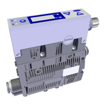
3 Product Description 3.2 Ejector Structure Blow off valve screw Compressed air connection (marking 1 [P]) Vacuum connection (marking 2 [V]) Silencer cover Display and operating element Mounting hole (2x) M12 electrical connection Exhaust outlet (marking 3) Control Power blow-off module for variant M EN-US ·... -
Page 12: Display And Operating Element In Detail
3 Product Description 3.3 Display and Operating Element in Detail The ejector is fitted with 3 buttons, the 3-digit display and 4 LEDs for status information to ensure simple operation. MENU BUTTON UP BUTTON Display LED vacuum limit value SP2 LED vacuum limit value SP1 LED process state “suction”... - Page 13 3 Product Description Meaning of the Vacuum Limit Value LEDs The LEDs for the switching points SP1 and SP2 (limit values) indicate the current level of the system vac- uum relative to the limit values set for the parameters: • SP1 —>...
-
Page 14: Operating And Menu Concept
4 Operating and Menu Concept 4 Operating and Menu Concept The device is operated using three buttons on the foil keypad: MENU DOWN The following information can be shown on the display: • The current vacuum measurement value • The selected menu item •... - Page 15 4 Operating and Menu Concept Deactivating the keypad lock: 4 Hold down the MENU button for 3 seconds. ð VNC appears on the display. ð The keypad lock is deactivated. The slideshow operates even when the keypad lock is activated. 4.1.3 Opening the Menu Pressing the DOWN button opens the main menu: 4 Press the DOWN button briefly.
-
Page 16: Main Menu
4 Operating and Menu Concept 4.2 Main Menu All settings for standard applications can be accessed and configured using the main menu. 4.2.1 Functions in the Main Menu The following table shows an overview of the display codes and parameters in the main menu: Display Parameter Explanation... -
Page 17: Extended Functions Menu (Ef)
4 Operating and Menu Concept 4.3 Extended Functions menu (EF) An Extended Functions menu (EF) is available for applications with special requirements. 4.3.1 Functions in the Extended Functions menu (EF) The following table shows an overview of the display codes and parameters in the Extended Functions menu. -
Page 18: Info Menu [Inf]
4 Operating and Menu Concept 8. Press the MENU button to save the changed value. ð If the entered value is within the permissible value range, it is accepted and the modified parameter is displayed. ð If the entered value is not within the permissible value range, this is briefly indicated on the display [1nc] and the new value is not accepted. -
Page 19: Overview Of Display Codes
4 Operating and Menu Concept 3. Use the DOWN and UP buttons to display or scroll through the blocks that make up the value. 4.5 Overview of Display Codes Display Parameter Comment code Switching point 1 Value at which the control function deactivates Reset point 1 Reset value 1 for the control function Switching point 2... - Page 20 4 Operating and Menu Concept Display Parameter Comment code Present vacuum exceeds the measurement range Overpressure in vacuum circuit; this normally happens exclusively in blow off mode. 20 / 56 EN-US · 30.30.00.04157 · 00 · 04/24...
-
Page 21: Technical Data
5 Technical Data 5 Technical Data 5.1 Display Parameters Parameter Value Unit Comment Display digit Red 7-segment LED display Solution ±1 mbar — Accuracy ±3 % FS = 25° C, based on FS (full-scale) final value Linearity error ±1 — Offset error ±2 mbar After zero-point adjustment, without vacuum Temperature influ-... -
Page 22: Electrical Parameters
5 Technical Data 5.3 Electrical Parameters Parameter Symbol Limit values Unit Comment min. typ. max. Supply voltage 19.2 26.4 V DC PELV Power consumption from U ̶ ̶ ̶ ̶ ̶ — — = 24.0 V with NO variant Power consumption from U ̶... -
Page 23: Dimensions
5 Technical Data Type SCPSi-2-07 SCPSi-2-9 SCPSi-2-14 Nozzle size [mm] Max. vacuum [mbar] Suction rate [l/min] Max. blow off capacity [l/min] Air consumption (suction) (l/min] 40.5 Sound level , unobstructed suction [dB(A)] Sound level , suction [dB(A)] Weight [kg] 0.195 At 4.0 bar 5.5 Dimensions Version without power blow-off... -
Page 24: Factory Settings
5 Technical Data Version with power blow-off (M) (d1) (d2) 18.6 6 / 8 6 / 8 1/8" 1/8" M12x 117.8 59.6 66.35 inter- inter- 1 ex- ternal threa threa threa 16.5 21.8 83.8 91.5 29.5 54.8 36.9 Depending on the design of the push-in connection. All specifications are in mm 5.6 Factory Settings Code... -
Page 25: Pneumatic Circuit Plans
5 Technical Data 5.7 Pneumatic Circuit Plans The pneumatic circuit diagrams are shown in simplified form. No sieve is installed in variants with a push- in connection. Key: Normally closed Normally open Power blow off Compressed air connection Vacuum connection Exhaust outlet Single-stage variants ...NO... - Page 26 5 Technical Data M...NO... M...NC... Two-stage variants ...NO..NC... 26 / 56 EN-US · 30.30.00.04157 · 00 · 04/24...
-
Page 27: Description Of Functions
6 Description of Functions 6 Description of Functions 6.1 Applying Suction to the Workpiece/Part (Vacuum Generation) WARNING The Compressed Air Supply of the Vacuum Generator Fails During Operation. Danger of falling parts because the vacuum for the vacuum gripper collapses quickly. 4 Ensure that the compressed air supply does not fail during operation. 4 Carry out a risk assessment for each application. -
Page 28: Depositing The Workpiece/Part (Blowing Off)
6 Description of Functions The ejector has an integrated air saving function and automatically regulates the vacuum in suction mode: • The electronics switch the Venturi nozzle off as soon as the vacuum limit value set for switching point SP1 is reached. •... - Page 29 6 Description of Functions 6.3.2 Manual Operating Mode WARNING Through an external signal, manual operation is exited, external signals are evaluated and system parts move. Personal injury or damage to property due to collisions 4 Ensure that the danger zone of the system is clear of people during operation. 4 Wear the required personal protective equipment (PPE) when working in the danger zone.
-
Page 30: Monitoring The System Vacuum And Defining Limit Values
6 Description of Functions Manual blow off ü The device is in manual mode. The SP1 and SP2 LEDs flash. 4 Press and hold the DOWN button to activate “blow off” on the ejector. ð The blow-off LED lights up. ð... -
Page 31: Control Functions
6 Description of Functions 2. Confirm using the MENU button. 3. Use the DOWN button to choose between [NO] and [YE5] (vacuum sensor calibration). 4. Confirm using the MENU button. ð The sensor is calibrated. 6.6 Control functions The ejector allows you to conserve compressed air or prevent a too powerful vacuum from being gener- ated. -
Page 32: Changing The Blow-Off Flow Rate On The Ejector
6 Description of Functions Set the time for time-controlled blow off (only active if value > 0). If you set the value to 0, the ejector is automatically in “externally controlled blow off” mode. 6.8 Changing the Blow-Off Flow Rate on the Ejector Do not overwind past the stop on the valve screw. -
Page 33: Counters
6 Description of Functions WARNING By activating/deactivating the product, output signals lead to an action in the production process! Personal injury 4 Avoid possible danger zone. 4 Remain vigilant. A description of how to reset the ejector to factory settings using the display and operating element fol- lows: ü... -
Page 34: Displaying The Software Version
6 Description of Functions The counter total is comprised of 3 blocks of digits: Displayed section 0. 4 8 61. 8 Digit block The current counter total in this example is 48 618 593. 6.12 Displaying the Software Version The software version indicates the software currently running on the internal controller. Using the control panel: ü... -
Page 35: Condition Monitoring (Cm)
6 Description of Functions 2. Use the MENU button to confirm the serial number parameter 5nr. ð The first three decimal places of the serial number are displayed (the digits x 10 ). This corre- sponds to the three-digit block with the highest value. 3. - Page 36 6 Description of Functions After 5 correctly measured evacuation times, the error message t-1 is reset. The message is also immedi- ately deleted if you set the permissible evacuation time to the value 000. 6.15.2 Leakage monitoring Vacuum Time Measuring the leakage: In control mode ([ctr] = [on]), the vacuum drop/leakage over a certain period of time is measured (as vacuum drop per unit time in mbar/s) from the point when the air saving function interrupts suction after reaching switching point SP1.
-
Page 37: Checking The Delivery
1. Compare the entire delivery with the supplied delivery notes to make sure nothing is missing. 2. Damage caused by defective packaging or occurring in transit must be reported immediately to the carrier and J. Schmalz GmbH. EN-US · 30.30.00.04157 · 00 · 04/24... -
Page 38: Installation
8 Installation 8 Installation 8.1 Installation Instructions CAUTION Improper installation or maintenance Injury to persons or damage to property 4 During installation and maintenance, make sure that the product is disconnected and depressurized and that it cannot be switched on again without authorization. To ensure safe installation, the following instructions must be observed: •... -
Page 39: Mounting
8 Installation 8.2 Mounting The ejector can be installed in any position. There are two 4.4 mm mounting holes for mounting the ejector. A DIN rail mount for DIN rail TS35 can be used as a mounting option. DIN rail mount for TS35 DIN rail, incl. plas- 2x M4 fastening screws with washers tic tapping screws Max. - Page 40 8 Installation CAUTION Noise pollution due to incorrect installation of the pressure and vacuum connections Hearing damage! 4 Correct installation. 4 Wear ear protectors. NOTE Operating pressure above the recommended maximum pressure Product damage 4 Only use the Ejector within the nominal pressure range. 8.3.1 Connecting the Compressed Air and Vacuum The compressed air connection is marked with the number 1 on the ejector.
-
Page 41: Electrical Connection
8 Installation The following table shows the recommended line cross-sections (internal diameter): Performance class Line cross-section (internal diameter) in mm Pressure side Vacuum side 2-07 2-09 2-14 Based on a maximum hose length of 2 m. 4 For longer hose lengths, the cross-sections must also be larger. 8.4 Electrical connection WARNING Electric shock... -
Page 42: Process Data
8 Installation The ejector can: • be connected directly to the controller, for example, using connection cable part no. 21.04.05.00080, or • use an IN/OUT box. Ensure that: • The electrical supply cable does not exceed the maximum length of 20 me- ters and •... -
Page 43: Start Of Operations
8 Installation The basic device functions such as suction, blow off and feedback are used with these signals. In detail, they are: Process data INPUT Signal Symbol Parameter OUT1 Vacuum limit value SP2 (“Part Present” check) Process data OUTPUT Signal Symbol Parameter Suction ON/OFF... -
Page 44: Operation
9 Operation 9 Operation 9.1 Safety Instructions for Operation WARNING Change of output signals when product is switched on or plug is connected Risk of injury to persons and damage to property due to uncontrolled movements of the higher-level machine/system! 4 The electrical connection must be performed only by specialists who can evaluate the effects of signal changes on the overall system. -
Page 45: Troubleshooting
10 Troubleshooting 10 Troubleshooting 10.1 Help with Malfunctions Fault Possible cause Solution 4 Make sure device is properly con- Power supply disrupted Electrical connection nected to power No communication Incorrect electrical connection 4 Check electrical connection and pin assignment 4 Check the controller configuration Higher-level controller not cor- rectly configured 4 Check electrical connection and pin... -
Page 46: Error Messages
10 Troubleshooting 10.2 Error messages If an error occurs, it appears on the display in the form of an error code (“E number”). The ejector’s re- sponse to an error depends on the type of error. Display code Error description Zero-point adjustment outside ±3% FS (full scale) Supply voltage is too low Supply voltage is too high Present vacuum exceeds the measurement range... -
Page 47: Maintenance
11 Maintenance 11 Maintenance 11.1 Safety Instructions Maintenance work may only be carried out by qualified personnel. 4 Create atmospheric pressure in the ejector’s compressed air circuit before working on the system! WARNING Failure to follow the instructions in these Operating instructions may result in in- juries! 4 Read the Operating instructions carefully and observe the contents. -
Page 48: Replacing The Silencer
11 Maintenance 11.3 Replacing the Silencer Heavy infiltration of dust, oil, and so on, may contaminate the silencer (2) and reduce the suction capac- ity. Cleaning the silencer is not recommended due to the capillary effect of the porous material. If the suction capacity decreases, replace the silencer (2): 1. -
Page 49: Replacing The Press-In Screens
11 Maintenance 11.4 Replacing the Press-In Screens The vacuum and compressed air connections of the ejectors contain press-in screens in the threaded version. Dust, chippings and other solid materials may be deposited in the screens over time. If there is a noticeable reduction in the performance of the ejectors, replace the filter screens (part no. 10.02.02.04404): 1. -
Page 50: Warranty
12 Warranty 12 Warranty This system is guaranteed in accordance with our general terms of trade and delivery. The same applies to spare parts, provided that these are original parts supplied by us. We are not liable for any damage resulting from the use of non-original spare parts or accessories. The exclusive use of original spare parts is a prerequisite for the proper functioning of the ejector and for the validity of the warranty. -
Page 51: Spare And Wearing Parts
13 Spare and wearing parts 13 Spare and wearing parts Maintenance work may only be carried out by qualified personnel. 4 WARNING! Risk of injury due to improper maintenance! After performing any maintenance or repair work, check that the system is functioning correctly, particularly the safety features. The following list contains the primary spare parts. -
Page 52: Accessories
14 Accessories 14 Accessories Part no. Designation Note 21.04.05.00080 Connection cable M12, 5-pin, with open end, 5 m 21.04.05.00086 Connection cable Socket to 2-pin cable, 3 m 21.04.05.00158 Connection cable 5-pin M12 socket, to 5-pin M12 connector, 1 m 21.04.05.00211 Connection cable 5-pin M12 socket, to 5-pin M12 connector, 2 m 10.02.02.03490 Connection distributor M12, 5-pin, to 2xM12, 4-pin... -
Page 53: Disposing Of The Product
For proper disposal, please contact a company specializing in the disposal of technical goods and instruct the company to observe the applicable disposal and environmental regulations. Schmalz is happy to assist you in finding a suitable company. EN-US · 30.30.00.04157 · 00 · 04/24... -
Page 54: Declarations Of Conformity
16 Declarations of Conformity 16 Declarations of Conformity 16.1 EC Conformity EU Declaration of Conformity The manufacturer Schmalz confirms that the product Ejector described in these Operating instructions ful- fills the following applicable EU directives: 2014/30/EU Electromagnetic Compatibility 2011/65/EU RoHS Directive The following harmonized standards were applied: EN ISO 12100... - Page 55 EN-US · 30.30.00.04157 · 00 · 04/24 55 / 56...
- Page 56 At Your Service Worldwide Vacuum automation Handling systems WWW.SCHMALZ.COM/AUTOMATION WWW.SCHMALZ.COM/EN-US/VACUUM-LIFTERS- AND-CRANE-SYSTEMS J. Schmalz GmbH Johannes-Schmalz-Str. 1 72293 Glatten, Germany T: +49 (0) 7443 2403-0 schmalz@schmalz.de WWW.SCHMALZ.COM...
Need help?
Do you have a question about the SCPSi-15 and is the answer not in the manual?
Questions and answers