
Subscribe to Our Youtube Channel
Related Manuals for Schmalz SCPS-UHV-HD


Summary of Contents for Schmalz SCPS-UHV-HD
- Page 1 SCPS-UHV-HD Compact Ejector Operating Instructions WWW.SCHMALZ.COM EN-US · 30.30.01.02657 · 00 · 01/21...
- Page 2 Published by © J. Schmalz GmbH, 01/21 This document is protected by copyright. J. Schmalz GmbH retains the rights established thereby. Repro- duction of the contents, in full or in part, is only permitted within the limits of the legal provisions of copyright law. Any modifications to or abridgments of the document are prohibited without explicit writ- ten agreement from J. Schmalz GmbH.
-
Page 3: Table Of Contents
Contents Contents 1 Important Information ........................... 5 Note on Using this Document ...................... 5 The technical documentation is part of the product ................ 5 Type Plate ............................ 5 Warnings in This Document........................ 6 Symbol.............................. 6 2 Fundamental Safety Instructions........................ 7 Safety .............................. 7 Intended Use............................ - Page 4 Contents 7 Installation.............................. 23 Installation Instructions........................ 23 Mounting ............................ 23 Pneumatic Connection ........................ 24 7.3.1 Connecting the Compressed Air and Vacuum ................. 24 Electrical connection ......................... 25 7.4.1 PIN Assignment.......................... 27 Process Data............................ 27 Start of Operations.......................... 28 8 Operation .............................. 29 Safety Instructions for Operation.....................
-
Page 5: Important Information
ð Failure to follow the instructions in these Operating instructions may result in injuries! ð Schmalz is not liable for damage or malfunctions that result from failure to heed these instructions. If you still have questions after reading the technical documentation, contact Schmalz Service at: www.schmalz.com/services... -
Page 6: Warnings In This Document
Important Information 1.4 Warnings in This Document Warnings warn against hazards that may occur when handling the product. The signal word indicates the level of danger. Signal word Meaning WARNING Indicates a medium-risk hazard that could result in death or serious injury if not avoided. -
Page 7: Fundamental Safety Instructions
Fundamental Safety Instructions 2 Fundamental Safety Instructions 2.1 Safety The ejector emits noise due to its use of compressed air. WARNING Noise pollution due to the escape of compressed air Hearing damage! 4 Wear ear protectors. 4 The ejector must only be operated with a silencer. WARNING Uncontrolled movements of system components or falling of objects caused by in- correct activation and switching of the Ejector while persons are in the plant... -
Page 8: Non-Intended Use
2.5 Modifications to the Ejector Schmalz assumes no liability for consequences of modifications over which it has no control: 1. The ejector must be operated only in its original condition as delivered. 2. Use only original spare parts from Schmalz. -
Page 9: Product Description
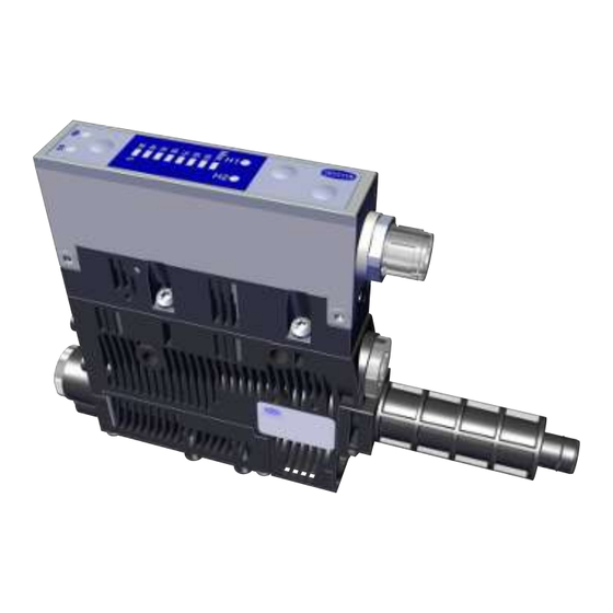
Product Description 3 Product Description 3.1 Ejector Designation The breakdown of the item designation (e.g. SCPS-UHV-HD 16 G02 NO PNP) is as follows: Property Variants Type of ejector SCPS-UHV-HD (Ultra High Vacuum-Heavy Duty) Nozzle size 0.7 mm; 1.1 mm; 1.6 mm Connection G02 (1/8" internal thread) -
Page 10: Display And Operating Element In Detail
Product Description 3.3 Display and Operating Element in Detail Simple ejector operation is ensured with 3 buttons, the bar display and 4 LEDs for status information. The current system vacuum is always displayed in the 8-digit LED bar display. MENU BUTTON LED bar display H1 limit value LED DOWN BUTTON... - Page 11 Product Description Meaning of the Vacuum Limit Value LEDs The LEDs for the vacuum limit values H1 and H2 indicate the current level of the system vacuum relative to the configured limit values. The display is independent of the switching function and the assignment of the output.
-
Page 12: Technical Data
Technical Data 4 Technical Data 4.1 Display Parameters Parameter Value Unit Comment Display Digit Red 7-segment LED display Resolution ±1 mbar — Accuracy ±3 % FS = 25° C, based on FS (full-scale) final value Linearity error ±1 — Offset error ±2 mbar After zero-point adjustment, without vacuum Temperature influ- ±3... -
Page 13: Factory Settings
Technical Data Parameter Symbol Limit values Unit Comment Current of signal input (PNP) — — — Current of signal input (NPN) — — — Reaction time of signal inputs — — — Reaction time of signal out- — Adjustable puts 1) The power supply must correspond to the regulations in accordance with EN60204 (protected extra-low voltage). -
Page 14: Dimensions
Technical Data 4.6 Dimensions 18.6 16.5 G1/8" G1/8" M12x 40.8 47.5 16.5 inter- inter- threa threa 31.5 91.5 83.8 36.9 All specifications are in mm 14 / 40 EN-US · 30.30.01.02657 · 00 · 01/21... -
Page 15: Pneumatic Circuit Plans
Technical Data 4.7 Pneumatic Circuit Plans SCPS...NO... SCPS...NC... EN-US · 30.30.01.02657 · 00 · 01/21 15 / 40... -
Page 16: General Description Of Functions
General Description of Functions 5 General Description of Functions 5.1 Picking up the Workpiece (Vacuum Generation) The ejector is designed for vacuum handling of airtight parts in combination with suction systems. The vacuum is generated in a nozzle according to the Venturi principle, using suction generated by the flow of accelerated compressed air. -
Page 17: Operation And Settings
General Description of Functions 5.3.1 Operation and Settings The three keys on the foil keypad are used for operation and setting the parameters. If no parameters are set, the ejector is in display mode. The current vacuum is displayed. If settings are changed, undefined states of the system may occur for a short time (for approx. 50 ms). 5.3.2 Manual Operating Mode WARNING Through an external signal, manual operation is exited, external signals are evalu-... -
Page 18: Viewing And Setting Parameters
General Description of Functions 5.4 Viewing and Setting Parameters The following parameters can be set for the ejector: • The vacuum limit value H1 for the control • The vacuum limit value H2 for the signal output • The blow off period for the time-controlled blow off The hystereses for the vacuum limit values are pre-defined. -
Page 19: Locking The Keypad
General Description of Functions 2. Change the selected parameter by pressing the button. ð The bar display LED increases or decreases. 3. Press the button to leave adjustment mode. ð The value will flash briefly to indicate that a changed parameter is being applied. 5.5 Locking the Keypad 4 Pressing the keys at the same time locks the keys. -
Page 20: Signal Type
General Description of Functions There is a valve screw below the vacuum connection that can be used to adjust the blow-off flow rate. The valve screw is equipped with a stop on both sides. Valve screw 1. Turn the valve screw clockwise to reduce the flow rate. 2. -
Page 21: Control Concept For Nc Ejectors
General Description of Functions 5.13 Control Concept for NC Ejectors “Suction” [IN1] “Blow off” [IN2] “Suction” state 0 bar “Blow off” state 0 bar 5.14 Vacuum unit The vacuum level in the LED bar is shown as a percentage of the maximum possible vacuum. If the vacuum is outside the permitted range, the LED next to this bar flashes rapidly. -
Page 22: Transport And Storage
1. Compare the entire delivery with the supplied delivery notes to make sure nothing is missing. 2. Damage caused by defective packaging or occurring in transit must be reported immediately to the carrier and J. Schmalz GmbH. 22 / 40 EN-US · 30.30.01.02657 · 00 · 01/21... -
Page 23: Installation
Installation 7 Installation 7.1 Installation Instructions CAUTION Improper installation or maintenance Personal injury or damage to property 4 During installation and maintenance, make sure that the ejector is disconnected and depressurized and that it cannot be switched on again without authorization. For safe installation, the following instructions must be observed: 1. -
Page 24: Pneumatic Connection
Installation The vacuum circuit is connected to the vacuum connection. The installation process is described and explained in detail below. 7.3 Pneumatic Connection CAUTION Compressed air or vacuum in direct contact with the eye Severe eye injury 4 Wear eye protection 4 Do not look into compressed air openings 4 Do not look into the silencer air stream 4 Do not look into vacuum openings, e.g. -
Page 25: Electrical Connection
Installation Compressed air connection Vacuum connection The G1/8" thread compressed air connection is marked with the number 1 on the ejector. 4 Connect the compressed air hose. The max. tightening torque is 3 Nm. The G1/8" vacuum connection is marked with the number 2 on the ejector. 4 Connect the vacuum hose. - Page 26 Installation NOTE Incorrect power supply Destruction of the integrated electronics 4 Operate the product using a power supply unit with protected extra-low voltage (PELV). 4 The system must incorporate safe electrical cut-off of the power supply in compliance with EN60204. 4 Do not connect or disconnect the connector under tension and/or when voltage is ap- plied.
-
Page 27: Pin Assignment
“Part Present” check signal output (H2/ Gray “Blow off” signal input When using Schmalz connection cable part no. 21.04.05.00080 7.5 Process Data During operation of the ejector, all input and output signals are connected to a controller, either directly or using intelligent terminal boxes. -
Page 28: Start Of Operations
Installation 7.6 Start of Operations A typical handling cycle is divided into the following three phases: pickup, blowoff and idle. To check whether sufficient vacuum has built up, the limit value H2 is monitored by an integrated vacuum sensor during suction and output to the higher-level controller via OUT. Phase Switching NC version... -
Page 29: Operation
Operation 8 Operation 8.1 Safety Instructions for Operation CAUTION Depending on the purity of the ambient air, the exhaust air can contain particles, which escape from the exhaust air outlet at high speed. Eye injuries 4 Do not look into the exhaust air flow 4 Wear eye protection CAUTION When the system is started in automatic operation, components move without ad-... -
Page 30: General Preparations
Operation 8.2 General Preparations Always carry out the following tasks before activating the system: 1. Before each start of operations, check that the safety features are in perfect condition. 2. Check the ejector for visible damage and deal with any problems immediately (or notify your super- visor). -
Page 31: Troubleshooting
4 Check the compressed air No compressed air supply supply. 4 Check the ejector and Ejector is faulty. contact Schmalz Service if necessary. 4 Replace screen Vacuum level is not reached Press-in screen in contami- or vacuum is created too... -
Page 32: Maintenance
Maintenance 10 Maintenance 10.1 Safety Maintenance work may only be carried out by qualified personnel. 4 Create atmospheric pressure in the ejector's compressed air circuit before working on the system! WARNING Risk of injury due to incorrect maintenance or troubleshooting 4 Check the proper functioning of the product, especially the safety features, after every maintenance or troubleshooting operation. -
Page 33: Cleaning Or Changing The Nozzle
Maintenance 2. Remove the silencer cover. 3. Replace the silencer insert (1). 10.4 Cleaning or Changing the Nozzle The easy access to the silencer insert and nozzle provided by the silencer cover with bayonet fastener en- sures that the nozzle is easy to clean and replace. ü... -
Page 34: Replacing The Press-In Screens
Maintenance 3. Install any cleaned or new nozzle in the cor- rect position. Ensure that the O-ring is fitted. O-Ring 10.5 Replacing the Press-In Screens The vacuum and compressed air connections of the ejectors contain press-in screens. Dust, chippings and other solid materials may be deposited in the screens over time. 4 If you notice that the performance of the ejectors has declined, replace the screens. -
Page 35: Warranty
Warranty 11 Warranty This system is guaranteed in accordance with our general terms of trade and delivery. The same applies to spare parts, provided that these are original parts supplied by us. We are not liable for any damage resulting from the use of non-original spare parts or accessories. The exclusive use of original spare parts is a prerequisite for the proper functioning of the ejector and for the validity of the warranty. -
Page 36: Spare And Wearing Parts, Accessories
Spare and Wearing Parts, Accessories 12 Spare and Wearing Parts, Accessories 12.1 Spare and Wearing Parts Maintenance work may only be carried out by qualified personnel. 4 WARNING! Risk of injury due to improper maintenance! After performing any maintenance or re- pair work, check that the system is functioning correctly, particularly the safety features. NOTE Incorrect maintenance work Damage to the ejector! -
Page 37: Decommissioning And Recycling
Decommissioning and Recycling 13 Decommissioning and Recycling 13.1 Disposing of the Ejector 1. Dispose of the product properly after replacement or decommissioning. 2. Observe the country-specific guidelines and legal obligations for waste prevention and disposal. 13.2 Materials Used Component Material Housing PA6-GF, PC-ABS Inner components Aluminum alloy, anodized aluminum alloy, brass, galvanized steel, stainless- steel, PU, POM... -
Page 38: Ec Conformity
EC Conformity 14 EC Conformity EU Conformity Declaration The manufacturer Schmalz confirms that the product Ejector described in these Operating instructions ful- fills the following applicable EU directives: 2014/30/EU Electromagnetic Compatibility 2011/65/EU RoHS Directive The following harmonized standards were applied: EN ISO 12100 Safety of machinery —... - Page 39 30.30.01.02657 · 00 · 02/21 39 / 40...
Need help?
Do you have a question about the SCPS-UHV-HD and is the answer not in the manual?
Questions and answers