
Related Manuals for Schmalz SCPSi-UHV-HD


Summary of Contents for Schmalz SCPSi-UHV-HD
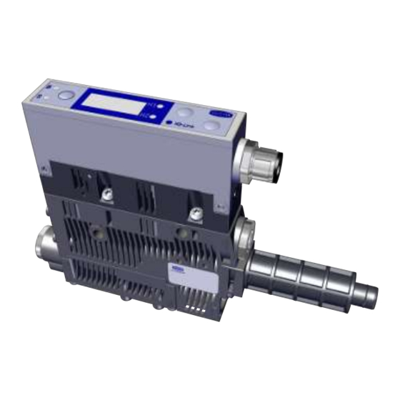
- Page 1 Compact Ejector SCPSi-UHV-HD Operating Instructions WWW.SCHMALZ.COM EN-US · 30.30.01.01484 · 00 · 01/21...
- Page 2 Published by © J. Schmalz GmbH, 01/21 This document is protected by copyright. J. Schmalz GmbH retains the rights established thereby. Repro- duction of the contents, in full or in part, is only permitted within the limits of the legal provisions of copyright law. Any modifications to or abridgments of the document are prohibited without explicit writ- ten agreement from J. Schmalz GmbH.
-
Page 3: Table Of Contents
Contents Contents 1 Important Information ........................... 6 Note on Using this Document ...................... 6 The technical documentation is part of the product ................ 6 Type Plate ............................ 6 Warnings in This Document........................ 7 Symbol.............................. 7 2 Fundamental Safety Instructions........................ 8 Safety .............................. 8 Intended Use............................ - Page 4 Contents Vacuum Monitoring .......................... 25 Control Function.......................... 25 Blow off Functions .......................... 26 Changing the Blow-Off Flow Rate on the Ejector................ 27 Monitoring the Supply Voltages ...................... 27 Evaluating the Inlet Pressure ...................... 28 7.10 Calibrating the Vacuum Sensor ...................... 28 7.11 Signal Output ............................
- Page 5 Contents 12 Warnings and Errors ............................. 51 12.1 Error Messages in SIO Operation...................... 51 12.2 Warnings and Error Messages in IO-Link Mode ................ 51 12.3 System Status Light in IO-Link Mode .................... 52 13 Maintenance.............................. 53 13.1 Safety .............................. 53 13.2 Cleaning the Ejector.......................... 53 13.3 Replacing the Silencer Insert ......................
-
Page 6: Important Information
ð Failure to follow the instructions in these Operating instructions may result in injuries! ð Schmalz is not liable for damage or malfunctions that result from failure to heed these instructions. If you still have questions after reading the technical documentation, contact Schmalz Service at: www.schmalz.com/services... -
Page 7: Warnings In This Document
Important Information 1.4 Warnings in This Document Warnings warn against hazards that may occur when handling the product. The signal word indicates the level of danger. Signal word Meaning WARNING Indicates a medium-risk hazard that could result in death or serious injury if not avoided. -
Page 8: Fundamental Safety Instructions
Fundamental Safety Instructions 2 Fundamental Safety Instructions 2.1 Safety The ejector emits noise due to its use of compressed air. WARNING Noise pollution due to the escape of compressed air Hearing damage! 4 Wear ear protectors. 4 The ejector must only be operated with a silencer. WARNING Uncontrolled movements of system components or falling of objects caused by in- correct activation and switching of the Ejector while persons are in the plant... -
Page 9: Non-Intended Use
2.5 Modifications to the Ejector Schmalz assumes no liability for consequences of modifications over which it has no control: 1. The ejector must be operated only in its original condition as delivered. 2. Use only original spare parts from Schmalz. -
Page 10: Product Description
Product Description 3 Product Description 3.1 Ejector Designation The breakdown of the item designation (e.g. SCPSi-UHV-HD 16 G02 NO) is as follows: Property Variants Type of ejector SCPSi-UHV-HD (ultra high vacuum-heavy duty) Nozzle size 0.7 mm; 1.1 mm; 1.6 mm Connection G02 (G1/8" internal thread) -
Page 11: Display And Operating Element In Detail
Product Description 3.3 Display and Operating Element in Detail Simple ejector operation is ensured with 3 buttons, the 3-digit display and 4 LEDs for status information. MENU BUTTON Display LED vacuum limit value H1 DOWN BUTTON UP BUTTON LED vacuum limit value H2 LED process state “suction”... - Page 12 Product Description Meaning of the Vacuum Limit Value LEDs The LEDs for the vacuum limit values H1 and H2 indicate the current level of the system vacuum relative to the configured limit values. Their display is independent of the switching function and assignment of the output, and independent of whether the condition monitoring function is active.
-
Page 13: Technical Data
Technical Data 4 Technical Data 4.1 Display Parameters Parameter Value Unit Comment Display Digit Red 7-segment LED display Resolution ±1 mbar — Accuracy ±3 % FS = 25° C, based on FS (full-scale) final value Linearity error ±1 — Offset error ±2 mbar After zero-point adjustment, without vacuum Temperature influ- ±3... -
Page 14: Factory Settings
Technical Data Parameter Symbol Limit values Unit Comment Current of signal input (PNP) — — — Current of signal input (NPN) — — — Reaction time of signal inputs — — — Reaction time of signal out- — Adjustable puts 1) The power supply must correspond to the regulations in accordance with EN60204 (protected extra-low voltage). -
Page 15: Performance Data
Technical Data 4.5 Performance Data Type SCPS UHV HD 07 SCPS UHV HD 11 SCPS UHV HD 16 Nozzle size [mm] Max. vacuum Suction rate [l/min] 27.8 53.2 Max. blow off capacity [l/min] Air consumption (suction) (l/min] 17.2 37.5 105.6 Sound level , unobstructed suction [dB(A)] Sound level... -
Page 16: Pneumatic Circuit Plans
Technical Data 4.7 Pneumatic Circuit Plans SCPSi...NO... SCPSi...NC... 16 / 72 EN-US · 30.30.01.01484 · 00 · 01/21... -
Page 17: Operating And Menu Concept
Operating and Menu Concept 5 Operating and Menu Concept The parameters can also be set using three buttons. The current system status and the settings are shown on a display. The unit is operated via three buttons on the foil keypad. Settings are configured using software menus. The operating structure is divided into settings in the main menu and configuration menu. -
Page 18: Configuration Menu
Operating and Menu Concept The following table shows an overview of the display codes in the main menu: Display code Parameter Explanation Vacuum limit value H1 Value at which the control function deactivates (only if ctr = on and oN5 are active) Hysteresis value h-1 Hysteresis value for the control function Vacuum limit value H2... -
Page 19: System Menu
Operating and Menu Concept Display Parameter Possible settings Explanation code Signal type PNP, input/output on = 24 V Signal type NPN, input/output on = 0 V Values: 10, 50, Delays the switching signals X1 and X2 H2 switching 200 and oFF signal delay Unit: milliseconds Vacuum unit Define the displayed vacuum unit... -
Page 20: Individual Functions
Operating and Menu Concept 5.5 Individual Functions Displaying the vacuum level: Outside of the menu, the ejector is in display mode and the current vacuum level is displayed. In display mode, a specific function is assigned to each key. Displaying the supply voltage: 4 Press the button ð... -
Page 21: Operating Modes
Operating Modes 6 Operating Modes All the ejectors in the SCPSi series can be operated in two operating modes: • Via direct connection to inputs and outputs (standard I/O = SIO) or • Connection via a communication line (IO-Link) By default, the ejector always runs in SIO mode, but it can be switched in and out of IO-Link mode by an IO-Link master at any time. -
Page 22: Process Data
Operating Modes 6.2.1 Process Data The cyclical process data is used to control the ejectors and receive current information reported from the ejector. There is a difference between the input data (Process Data In) and the controlling output data (Process Data Out). The input data Process Data In is used to report the following information cyclically: •... -
Page 23: General Description Of Functions
General Description of Functions 7 General Description of Functions 7.1 Picking up the Workpiece (Vacuum Generation) The ejector is designed for handling and holding workpieces by means of a vacuum in combination with suction systems. The vacuum is generated in a nozzle according to the Venturi principle, using suction generated by the flow of accelerated compressed air. -
Page 24: Operating Modes
General Description of Functions • Externally time-controlled blow off The current process state is indicated by the LED status indicators. During blow off, [-FF] is shown on the display. 7.3 Operating Modes The ejector can be operated in four operating modes: •... -
Page 25: Vacuum Monitoring
General Description of Functions Activating the Operating Mode Press and hold the button for more than 3 seconds. An M appears on the display while you do The current process state is retained. Manual suction button activates “suction” on the ejector. Press the button to exit the “suction”... -
Page 26: Blow Off Functions
General Description of Functions Operating mode Explanation No control/continuous suction, H1 The ejector produces continuous suction with maximum in hysteresis mode power. This setting is recommended for very porous workpieces, which would otherwise cause vacuum gener- [ctr] => [oFF] ation to switch on and off continuously due to the high rate of leakage. -
Page 27: Changing The Blow-Off Flow Rate On The Ejector
General Description of Functions Description Explanation The blow off signal overrides the suction signal, even if the specified blow off time is very long. The length of the blow off time [tbL] is set in the main menu. This menu item is suppressed in operating mode [-E-]. -
Page 28: Evaluating The Inlet Pressure
General Description of Functions • The pneumatic state of the ejector changes as follows: – For the NO-type ejector, the ejector switches to the “suction” operating state – For the NC-type ejector, the ejector switches to the “pneumatically OFF” operating state 7.9 Evaluating the Inlet Pressure The available supply pressure level in the system cannot be measured by the ejector itself. -
Page 29: Control Concept For No Ejectors
General Description of Functions 7.13 Control Concept for NO Ejectors “Suction” [IN1] “Blow off” [IN2] “Suction” state 0 bar “Blow off” state 0 bar 7.14 Control Concept for NC Ejectors “Suction” [IN1] “Blow off” [IN2] “Suction” state 0 bar “Blow off” state 0 bar 7.15 Vacuum unit You can choose between the following three units for the unit of the displayed vacuum level under the [uni] menu item in the configuration menu or via IO-Link. -
Page 30: Switch-Off Delay
General Description of Functions 7.16 Switch-off Delay You can use this function to set a switch-off delay for the H2 “Part Present” check signal. This can be used to mask short-term fluctuations in the vacuum level of the vacuum system. The duration of the switch-off delay can be set with the parameter [dlY] in the configuration menu or via IO-Link. -
Page 31: Resetting To Factory Settings
General Description of Functions 7.19 Resetting to Factory Settings This function restores the ejector configuration of the initial setup and the settings of the active produc- tion setup profile to the factory settings. WARNING By activating/deactivating the product, output signals lead to an action in the pro- duction process! Personal injury 4 Avoid possible danger zone. -
Page 32: Displaying The Software Version
General Description of Functions ü Select the counter you wish to see in the system menu. 4 Confirm the counter by pressing the button. ð The last three decimal places of the counter total are displayed (the digits x10 ). This corresponds to the least significant three digits. -
Page 33: Displaying The Serial Number
General Description of Functions 7.23 Displaying the serial number The serial number indicates the production period of the ejector. ü In the system menu, select the 5nr parameter. 1. Confirm using the button. ð The last three decimal places of the serial number are displayed (the digits x 10 ). -
Page 34: Condition Monitoring (Cm)
General Description of Functions 7.26.1 Condition Monitoring (CM) Monitoring the valve switching frequency: When the air saving function is activated and there is a high leakage level in the gripping system, the ejector switches between the suction and suction-off states very frequently. The number of valve switch- ing procedures thus increases rapidly within a short time. - Page 35 General Description of Functions Evacuation times t0 and t1 Vacuum [mbar] Suction ON Time [s] If the measured evacuation time t1 (from H2 to H1) exceeds the specified value [t-1], the “Evacuation time longer than t-1” condition monitoring warning is triggered and the system status light switches to yellow. The specified value for the max.
-
Page 36: Energy Monitoring (Em)
General Description of Functions Dynamic pressure monitoring: If possible, a dynamic pressure measurement is taken at the start of every suction cycle. The result of this measurement is compared to the vacuum limit values set for H1 and H2. If the dynamic pressure is greater than (H2 - h2) but less than H1, the corresponding condition monitoring warning will be set and the system status light will switch to yellow. -
Page 37: Diagnostic Buffer
General Description of Functions The measured value for the leakage rate and the related quality assessment in percent are reset at the start of every suction cycle and constantly updated during the cycle as moving averages. The values there- fore remain stable until after the suction cycle is complete. Measurement of dynamic pressure: This measures the system vacuum achieved during unobstructed suction. -
Page 38: Epc Values In The Process Data
General Description of Functions 7.26.6 EPC Values in the Process Data To quickly and easily capture the most important results from the condition monitoring [CM], energy monitoring and predictive maintenance functions, these are also made available via the process input data of the device. The top 3 bytes of the process output data are also configured as a multifunctional data range, consisting of an 8 bit value (“EPC Value 1”) and a 16 bit value (“EPC Value 2”). - Page 39 General Description of Functions "EPC-Select" [PDOut 0.5 …0.4] “EPC-Select-Acknowledge" [PDIn 0.3] “EPC Value 1” [PDIn 1] Pressur Pressur Leakage Pressur Voltage Pressur "EPC-Value 2" Dynamic [PDIn 3 … 2] Vacuum Evac. Time Vacuum Vacuum Air cons. Vacuum pressure Controller applies valid EPC values EN-US ·...
-
Page 40: Transport And Storage
1. Compare the entire delivery with the supplied delivery notes to make sure nothing is missing. 2. Damage caused by defective packaging or occurring in transit must be reported immediately to the carrier and J. Schmalz GmbH. 40 / 72 EN-US · 30.30.01.01484 · 00 · 01/21... -
Page 41: Installation
Installation 9 Installation 9.1 Installation Instructions CAUTION Improper installation or maintenance Personal injury or damage to property 4 During installation and maintenance, make sure that the ejector is disconnected and depressurized and that it cannot be switched on again without authorization. For safe installation, the following instructions must be observed: 1. -
Page 42: Pneumatic Connection
Installation The vacuum circuit is connected to the vacuum connection. The installation process is described and explained in detail below. 9.3 Pneumatic Connection CAUTION Compressed air or vacuum in direct contact with the eye Severe eye injury 4 Wear eye protection 4 Do not look into compressed air openings 4 Do not look into the silencer air stream 4 Do not look into vacuum openings, e.g. -
Page 43: Electrical Connection
Installation 1. Shorten the hoses and pipelines as much as possible. 2. Keep hose lines free of bends and crimps. 3. Only use a hose or pipe with the recommended internal diameter to connect the product; otherwise, use the next largest diameter. - On the compressed air side, ensure that the internal diameter has the dimensions required for the product to achieve its performance data. -
Page 44: Pin Assignment
Supply voltage for sensors/actuators White “Suction” signal input Blue Ground for sensors/actuators Black “Part Present” check signal output (H2/ Gray “Blow off” signal input When using Schmalz connection cable part no. 21.04.05.00080 44 / 72 EN-US · 30.30.01.01484 · 00 · 01/21... -
Page 45: Pin Assignment In Io-Link Mode
Gray — — 1) When using Schmalz connection cable part no. 21.04.05.00080 9.5 Start of Operations A typical handling cycle is divided into the following three phases: pickup, blowoff and idle. To check whether sufficient vacuum has built up, the limit value H2 is monitored by an integrated vacuum sensor during suction and output to the higher-level controller via OUT. -
Page 46: Operation
Operation 10 Operation 10.1 Safety Instructions for Operation CAUTION Depending on the purity of the ambient air, the exhaust air can contain particles, which escape from the exhaust air outlet at high speed. Eye injuries 4 Do not look into the exhaust air flow 4 Wear eye protection CAUTION When the system is started in automatic operation, components move without ad-... -
Page 47: Typical Suction Cycles
Operation 10.3 Typical Suction Cycles The diagrams below show some typical vacuum processes during a suction cycle. The diagrams also indi- cate the times at which EPC measured values are updated. Handling cycle with dynamic pressure measurement and average leakage: Typical suction cycle SUCTION BLOW NEUTRAL... - Page 48 Operation Handling cycle with dynamic pressure measurement and excessive leakage: Typical suction cycle SUCTION BLOW NEUTRAL SUCTION Vacuum Condition monitoring Evacuation time t0 Evacuation time t1 Dynamic pressure Leakage Air consumption El. energy consumption Handling cycle with leakage > L and readjustment: Typical suction cycle SUCTION BLOW...
- Page 49 Operation Handling cycle with very high leakage (H1 is not reached): Typical suction cycle SUCTION BLOW NEUTRAL SUCTION Vacuum Condition monitoring Evacuation time t0 Evacuation time t1 Dynamic pressure Leakage Air consumption El. energy consumption Handling cycle with excessive evacuation time t1: Typical suction cycle SUCTION BLOW...
-
Page 50: Troubleshooting
4 Check the compressed air No compressed air supply supply. 4 Check the ejector and Ejector is faulty. contact Schmalz Service if necessary. 4 Replace screen Vacuum level is not reached Press-in screen in contami- or vacuum is created too... -
Page 51: Warnings And Errors
Warnings and Errors 12 Warnings and Errors 12.1 Error Messages in SIO Operation When a known error occurs, this is reported in the form of an error number. In SIO mode, error messages are shown on the display. An “E” followed by the error number appears on the display. The following table shows all the error codes: Code dis- Explanation... -
Page 52: System Status Light In Io-Link Mode
Warnings and Errors Any condition monitoring events that occur during the suction cycle cause the system status indicator light to immediately switch from green to yellow/orange. The event that caused this switch can be seen in the “Condition monitoring” IO-Link parameter. The table below explains the coding of the condition monitoring warnings: Event Update... -
Page 53: Maintenance
Maintenance 13 Maintenance 13.1 Safety Maintenance work may only be carried out by qualified personnel. 4 Create atmospheric pressure in the ejector's compressed air circuit before working on the system! WARNING Risk of injury due to incorrect maintenance or troubleshooting 4 Check the proper functioning of the product, especially the safety features, after every maintenance or troubleshooting operation. -
Page 54: Cleaning Or Changing The Nozzle
Maintenance 2. Remove the silencer cover. 3. Replace the silencer insert (1). 13.4 Cleaning or Changing the Nozzle The easy access to the silencer insert and nozzle provided by the silencer cover with bayonet fastener en- sures that the nozzle is easy to clean and replace. ü... -
Page 55: Replacing The Press-In Screens
Maintenance 3. Install any cleaned or new nozzle in the cor- rect position. Ensure that the O-ring is fitted. O-Ring 13.5 Replacing the Press-In Screens The vacuum and compressed air connections of the ejectors contain press-in screens. Dust, chippings and other solid materials may be deposited in the screens over time. 4 If you notice that the performance of the ejectors has declined, replace the screens. -
Page 56: Warranty
Warranty 14 Warranty This system is guaranteed in accordance with our general terms of trade and delivery. The same applies to spare parts, provided that these are original parts supplied by us. We are not liable for any damage resulting from the use of non-original spare parts or accessories. The exclusive use of original spare parts is a prerequisite for the proper functioning of the ejector and for the validity of the warranty. -
Page 57: Spare And Wearing Parts, Accessories
Spare and Wearing Parts, Accessories 15 Spare and Wearing Parts, Accessories 15.1 Spare and Wearing Parts Maintenance work may only be carried out by qualified personnel. 4 WARNING! Risk of injury due to improper maintenance! After performing any maintenance or re- pair work, check that the system is functioning correctly, particularly the safety features. NOTE Incorrect maintenance work Damage to the ejector! -
Page 58: Decommissioning And Recycling
Decommissioning and Recycling 16 Decommissioning and Recycling 16.1 Disposing of the Ejector 1. Dispose of the product properly after replacement or decommissioning. 2. Observe the country-specific guidelines and legal obligations for waste prevention and disposal. 16.2 Materials Used Component Material Housing PA6-GF, PC-ABS Inner components Aluminum alloy, anodized aluminum alloy, brass, galvanized steel, stainless- steel, PU, POM... -
Page 59: Attachment
Attachment 17 Attachment See also 2 SCPSi_V2 Data Dictionary 21.10.01.00065_02 2014-08-29.pdf [} 61] 17.1 Overview of the Display Codes Code Parameter Comment Limit value H1 Switch-off value for air-saving function/control Hysteresis value h1 Hysteresis of control Limit value H2 Switch-on value of the “Part Present” signal output (when the NO output is configured) Hysteresis value h2 Hysteresis of “Part Present”... -
Page 60: Ec Conformity
The buttons and menus are unlocked. Reset All adjustable values are reset to the factory settings. 17.2 EC Conformity EU Conformity Declaration The manufacturer Schmalz confirms that the product Ejector described in these Operating instructions ful- fills the following applicable EU directives: 2014/30/EU Electromagnetic Compatibility 2011/65/EU... - Page 61 IO-Link Data Dictionary SCPSi series 21.10.01.00065/02 29.08.2014 J. Schmalz GmbH Aacher Straße 29, D 72293 Glatten Tel.: +49(0)7443/2403-0 Fax: +49(0)7443/2403-259 info@schmalz.de IO-Link Implementation IO-Link Version 1.1 IO-Link Version 1.0 (legacy mode) Vendor ID 234 (0x00EA) 234 (0x00EA) Device ID 100243 (0x018793)
- Page 62 IO-Link Data Dictionary SCPSi series 21.10.01.00065/02 29.08.2014 J. Schmalz GmbH Aacher Straße 29, D 72293 Glatten Tel.: +49(0)7443/2403-0 Fax: +49(0)7443/2403-259 info@schmalz.de Process Data Out Name Bits Access Availability Remark Vacuum IO-Link V1.1, V1.0 Vacuum on/off Blow-off IO-Link V1.1, V1.0 Activate Blow-off...
- Page 63 IO-Link Data Dictionary SCPSi series 21.10.01.00065/02 29.08.2014 J. Schmalz GmbH Aacher Straße 29, D 72293 Glatten Tel.: +49(0)7443/2403-0 Fax: +49(0)7443/2403-259 info@schmalz.de 0x0012 Product name 8 bytes SCPSi_V2 General product name Product text 0x0014 30 bytes SCPSi 00 G2 NC M12-5 Order-Code...
- Page 64 IO-Link Data Dictionary SCPSi series 21.10.01.00065/02 29.08.2014 J. Schmalz GmbH Aacher Straße 29, D 72293 Glatten Tel.: +49(0)7443/2403-0 Fax: +49(0)7443/2403-259 info@schmalz.de 0 = off 0x004E dCS Disable continuous suction 1 byte 0 - 1 1 = on 0x0064 H-1 Setpoint H1 2 bytes 998 >= H1 >= (H2+h1)
- Page 65 IO-Link Data Dictionary SCPSi series 21.10.01.00065/02 29.08.2014 J. Schmalz GmbH Aacher Straße 29, D 72293 Glatten Tel.: +49(0)7443/2403-0 Fax: +49(0)7443/2403-259 info@schmalz.de 0x00D0 Permissible leakage rate 2 bytes 1 - 999 Production Setup - Profile P3 Profile P-3 0x00DC Air saving function...
- Page 66 IO-Link Data Dictionary SCPSi series 21.10.01.00065/02 29.08.2014 J. Schmalz GmbH Aacher Straße 29, D 72293 Glatten Tel.: +49(0)7443/2403-0 Fax: +49(0)7443/2403-259 info@schmalz.de Diagnosis Error 0x0082 Exx Active error code 1 byte 1-99 = Error code displayed by the device ...
- Page 67 IO-Link Data Dictionary SCPSi series 21.10.01.00065/02 29.08.2014 J. Schmalz GmbH Aacher Straße 29, D 72293 Glatten Tel.: +49(0)7443/2403-0 Fax: +49(0)7443/2403-259 info@schmalz.de Predictive Maintenance [PM] Leakage rate 0x00A0 2 bytes Leakage of last suction cycle (unit: 1 mbar/sec) 0x00A1 Free-flow vacuum...
- Page 68 IO-Link Data Dictionary SCPSi series 21.10.01.00065/02 29.08.2014 J. Schmalz GmbH Aacher Straße 29, D 72293 Glatten Tel.: +49(0)7443/2403-0 Fax: +49(0)7443/2403-259 info@schmalz.de Availability of EPC data during suction cycle J. Schmalz GmbH 8 of 11 SCPSi Data Dictionary...
- Page 69 IO-Link Data Dictionary SCPSi series 21.10.01.00065/02 29.08.2014 J. Schmalz GmbH Aacher Straße 29, D 72293 Glatten Tel.: +49(0)7443/2403-0 Fax: +49(0)7443/2403-259 info@schmalz.de Diagnostic Buffer - Details Data Format of Single Entry (ISDU 132) Bytes 0…1 Bytes 2…5 Remark Diagnostic-Type (MSB first)
- Page 70 IO-Link Data Dictionary SCPSi series 21.10.01.00065/02 29.08.2014 J. Schmalz GmbH Aacher Straße 29, D 72293 Glatten Tel.: +49(0)7443/2403-0 Fax: +49(0)7443/2403-259 info@schmalz.de 0x0208 Error E08 disappeared: IO-Link communication interrupted 0x120C Error E12 appeared: Short-circuit at OUT2 0x020C Error E12 disappeared: Short-circuit at OUT2...
- Page 71 IO-Link Data Dictionary SCPSi series 21.10.01.00065/02 29.08.2014 J. Schmalz GmbH Aacher Straße 29, D 72293 Glatten Tel.: +49(0)7443/2403-0 Fax: +49(0)7443/2403-259 info@schmalz.de EPC Data Buffer - Details Data Format of Single Entry (ISDU 134) Bytes 0…1 Bytes 2…3 Bytes 4…5 Bytes 6…9...
Need help?
Do you have a question about the SCPSi-UHV-HD and is the answer not in the manual?
Questions and answers