Table of Contents
Advertisement
Quick Links
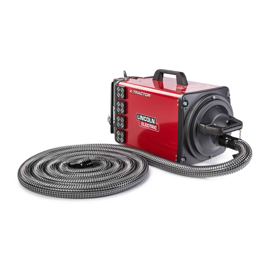
X-TRACTOR ® 1GC
For use with machines having Code Numbers:
K652-1, K652-2
SERVICE MANUAL
SVM250
| Issue D ate 14-Jun
© Lincoln Global, Inc. All Rights Reserved.
NOTE: This manual will cover most of the troubleshooting and repair
procedures for the code numbers listed. Some variances may exist when
troubleshooting/repairing later code numbers.
Advertisement
Table of Contents
Troubleshooting

Related Manuals for Lincoln Electric K652-1


Summarization of Contents
SERVICE MANUAL
X-TRACTOR 1GC
Identification of the welding equipment covered by this manual.
SAFETY
Fume and Ventilation Safety
Guidance on protecting yourself from welding fumes and gases.
Personal Protective Equipment
Mandatory personal protective equipment for welding operations.
Engine Powered Equipment Safety
Safety precautions specific to operating engine-powered equipment.
Electric Shock Hazards
Critical safety warnings and procedures to prevent fatal electric shock.
Arc Ray and Fume Hazards
Protective measures against arc rays, fumes, and gases.
Fire, Explosion, and Cylinder Safety
Safety measures to prevent fires, explosions, and cylinder damage.
ELECTROMAGNETIC COMPATABILITY (EMC)
EMC Conformance and Introduction
Declaration of conformity and explanation of EMC principles.
Installation and Emission Reduction Methods
User responsibilities and techniques for mitigating EMC disturbances.
BIBLIOGRAPHY AND SUGGESTED READING
Welding Electrode Ingredient Exposure Limits
Reference table for welding electrode ingredients, TLV, and PEL exposure limits.
THEORY OF OPERATION
Input Power and Line Switch
Details on how input power and the line switch function.
Key Component Interactions
Explanation of the interplay between switches, PC board, thyristor, and motors.
Auto/Manual Switch and Current Sensor
How the auto/manual switch and current sensor interact.
TROUBLESHOOTING AND REPAIR
How to Use Troubleshooting Guide
Instructions on how to effectively use the troubleshooting guide.
PC Board Troubleshooting Procedures
Steps for diagnosing and resolving issues with the PC board.
Troubleshooting Guide Overview
A structured guide to identify and resolve common machine problems.
Case Cover Removal and Replacement
Detailed steps for safely removing and reinstalling machine covers.
Current Sensor Test
Procedure to verify the functionality of the current sensor.
Thyristor Test
Method to test the thyristor for proper operation.
PC Board Test
Procedure to diagnose the PC board's operational status.
Line Switch Test
Steps to check the functionality of the main line switch.
Mode Switch Test
Procedure to verify the correct operation of the mode switch.
Motor M2 (Low) Test
Diagnostic test for Motor M2 when operating in low mode.
Motor M1 (High) Test
Diagnostic test for Motor M1 when operating in high mode.
Current Sensor Removal and Replacement
Guide for removing and replacing the current sensor.
Thyristor Removal and Replacement
Instructions for removing and replacing the thyristor component.
PC Board Removal and Replacement
Procedure for removing and replacing the main PC board.
Line Switch Removal and Replacement
Steps for removing and replacing the line switch.
Mode Switch Removal and Replacement
Procedure for removing and replacing the mode switch.
Motor Removal and Replacement
Guide for removing and replacing the machine's motors.
DIAGRAMS
Wiring Diagram: Pre-May 1997 Models
Wiring diagram for models manufactured before May 1997 (without Low/High Switch).
Wiring Diagram: May 1997-April 1999 Models
Wiring diagram for models manufactured May 1997-April 1999 (with Low/High Switch).
Wiring Diagram: Post-April 1999 Models
Wiring diagram for models manufactured after April 1999 (with Low/High Switch).
Need help?
Do you have a question about the K652-1 and is the answer not in the manual?
Questions and answers