Advertisement
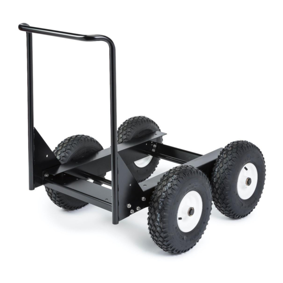
K3590-1 - RANGER UNDERCARRIAGE (ALL TERRAIN)
REQUIRED TOOLS
• 9/16" Wrench and Socket
• 1/2" Wrench and Socket
• TORX T-30 Bit or Driver
• Grease Gun
•
Hammer or Mallet
• Crane or Hoist
2
4
1
5
6
WARNING
Push only from the front using the
Undercarriage handle.
CAUTION
times.
IM10503 Feb-19 ©Lincoln Global Inc. The graphics may not exactly reflect the latest design.
PARTS INCLUDED
1
2
7
3
4
5
3
6
8
7
8
L17286
SIDE RAIL
T8833-86
3/8-16 X 1.25" HHCS
CF000067
3/8-16 HEX NUT
S9262-120
3/8" PLAIN WASHER
E106A-16
3/8" LOCKWASHER
L17287
SIDE RAIL
T8833-86
3/8-16 X 1.25" HHCS
CF000067
3/8-16 HEX NUT
S9262-120
3/8" PLAIN WASHER
E106A-16
3/8" LOCKWASHER
L17288
S24739-43
5/16-18 X .75" HHCS
S9262-121
5/16" PLAIN WASHER
CF000029
5/16-18 HEX NUT
E106A-14
5/16" LOCKWASHER
L17289
REAR CROSSMEMBER
S24739-43
5/16-18 X .75" HHCS
S9262-121
5/16" PLAIN WASHER
CF000029
5/16-18 HEX NUT
E106A-14
5/16" LOCKWASHER
M26317
AXLE SHAFT
S32770
PNEUMATIC WHEEL
S32843
E-CLIP
S9262-24
1.00" PLAIN WASHER
G9190
HANDLE ASSEMBLY
S24739-43
5/16-18 X .75" HHCS
S9262-121
5/16" PLAIN WASHER
CF000029
5/16-18 HEX NUT
E106A-14
5/16" LOCKWASHER
S33350
LIMITER BRACKET
T8833-86
3/8-16 X 1.25" HHCS
CF000067
3/8-16 HEX NUT
S9262-120
3/8" PLAIN WASHER
E106A-16
3/8" LOCKWASHER
1
2
2
4
2
1
2
2
4
2
1
4
4
4
4
1
4
4
4
4
2
4
4
4
1
4
4
4
4
2
4
4
8
4
Advertisement
Table of Contents

Subscribe to Our Youtube Channel
Related Manuals for Lincoln Electric K3590-1


Summary of Contents for Lincoln Electric K3590-1
- Page 1 K3590-1 - RANGER UNDERCARRIAGE (ALL TERRAIN) REQUIRED TOOLS PARTS INCLUDED • 9/16” Wrench and Socket L17286 SIDE RAIL • 1/2” Wrench and Socket T8833-86 3/8-16 X 1.25" HHCS CF000067 3/8-16 HEX NUT • TORX T-30 Bit or Driver S9262-120 3/8" PLAIN WASHER •...
- Page 2 Step 1: Limiter Brackets Install the two limiter brackets to the front crossmember as shown. Using a 9/16” wrench and socket, attach with (4) 3/8”-16 x 1.25” hex head cap screw, (4) 3/8-16 hex head nuts, (8) 3/8” plain washers, (4) 3/8” lock washers. Torque the 3/8-16 bolts to 15 ft-lb. Figure A- 1...
- Page 3 Step 2: Front Crossmember Using a 1/2” wrench and socket, install the front crossmember (L17288) to the two side rails (L17286 & L17287). Use (4) 5/16-18 x 1.00 hex head cap screw, (4) 5/16-18 hex nuts, (4) 5/16” plain washers, and (4) 5/16” lock washers. Leave bolted connections finger tight. Figure A- 2...
- Page 4 Step 3: Rear Crossmember a. Using a 1/2” wrench and socket, install the rear crossmember (L17289) to the two side rails (L17286 & L17287). Use (4) 5/16-18 x 1.00 hex head cap screw, (4) 5/16-18 hex nuts, (4) 5/16” plain washers, and (4) 5/16” lock washers. Tighten all bolts on the front and rear crossmembers now.
- Page 5 Step 4: Axles and Wheels a. Slide each axle shaft (M26317) through the side rail holes. b. Push a wheel onto each end of the axle shaft with the longer hub oriented toward the side rail and the Air Valve hub side facing out. c.
- Page 6 Step 5: Bolting Machine to Undercarriage a. Place the machine on the undercarriage with a crane or hoist, aligning the (4) holes on the bottom of the machine with the (4) holes on the cart. The side doors will need to be removed to see the front (2) holes on the machine.
- Page 7 Figure A- 7 Step 6: Installing the Handle a. Remove (2) ¼-20 x .50” Pan Head screws using a T30 bit from the front left and front right sides of the welder. (Figure A-7) b. Using a 1/2” wrench and socket, install the handle assembly (G9190) to the two side rails (L17286 &...
Need help?
Do you have a question about the K3590-1 and is the answer not in the manual?
Questions and answers