Lincoln Electric X-TRACTOR 1GC Service Manual
Hide thumbs
Also See for X-TRACTOR 1GC:
- Technical specifications (4 pages) ,
- Operator's manual (20 pages)
Table of Contents
Advertisement
Quick Links
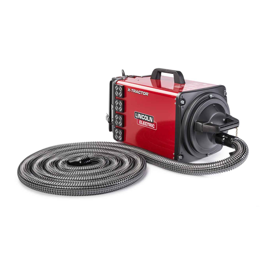
X-TRACTOR ® 1GC
For use with machines having Code Numbers:
K652-1, K652-2
SERVICE MANUAL
SVM250
| Issue D ate 14-Jun
© Lincoln Global, Inc. All Rights Reserved.
NOTE: This manual will cover most of the troubleshooting and repair
procedures for the code numbers listed. Some variances may exist when
troubleshooting/repairing later code numbers.
Advertisement
Table of Contents
Troubleshooting


Need help?
Do you have a question about the X-TRACTOR 1GC and is the answer not in the manual?
Questions and answers