Lincoln Electric POWER WAVE STT Operator's Manual
Module (ce)
Hide thumbs
Also See for POWER WAVE STT:
- Operator's manual (64 pages) ,
- Specification sheet (168 pages) ,
- Manual (9 pages)
Table of Contents
Advertisement
Quick Links
Operator's Manual
POWER WAVE
Register your machine:
www.lincolnelectric.com/register
Authorized Service and Distributor Locator:
www.lincolnelectric.com/locator
Save for future reference
Date Purchased
Code: (ex: 10859)
Serial: (ex: U1060512345)
IM10057-A
| Issue D ate Apr-18
© Lincoln Global, Inc. All Rights Reserved.
®
®
STT
MODULE (CE)
For use with machines having Code Numbers:
11680
Need Help? Call 1.888.935.3877
to talk to a Service Representative
Hours of Operation:
8:00 AM to 6:00 PM (ET) Mon. thru Fri.
After hours?
Use "Ask the Experts" at lincolnelectric.com
A Lincoln Service Representative will contact you
no later than the following business day.
For Service outside the USA:
Email: globalservice@lincolnelectric.com
Advertisement
Table of Contents

Related Manuals for Lincoln Electric POWER WAVE STT


Summary of Contents for Lincoln Electric POWER WAVE STT
- Page 1 Operator’s Manual ® ® POWER WAVE MODULE (CE) For use with machines having Code Numbers: 11680 Need Help? Call 1.888.935.3877 Register your machine: to talk to a Service Representative www.lincolnelectric.com/register Authorized Service and Distributor Locator: Hours of Operation: www.lincolnelectric.com/locator 8:00 AM to 6:00 PM (ET) Mon. thru Fri. Save for future reference After hours? Use “Ask the Experts”...
- Page 2 THANK YOU FOR SELECTING A QUALITY PRODUCT BY KEEP YOUR HEAD OUT OF THE FUMES. DON’T get too close to the arc. LINCOLN ELEC TRIC. Use corrective lenses if necessary to stay a reasonable distance away from the arc. READ and obey the Safety Data PLEASE EXAMINE CARTON AND EQUIPMENT FOR Sheet (SDS) and the warning label DAMAGE IMMEDIATELY...
- Page 3 W117.2-1974. A Free copy of “Arc Welding Safety” booklet E205 is available from the Lincoln Electric Company, 2.d. All welders should use the following procedures in order to 22801 St. Clair Avenue, Cleveland, Ohio 44117-1199.
- Page 4 SAFETY ELECTRIC SHOCK ARC RAYS CAN BURN. CAN KILL. 3.a. The electrode and work (or ground) circuits are 4.a. Use a shield with the proper filter and cover plates to protect your electrically “hot” when the welder is on. Do eyes from sparks and the rays of the arc when welding or not touch these “hot”...
- Page 5 SAFETY WELDING AND CUTTING CYLINDER MAY EXPLODE IF SPARKS CAN CAUSE DAMAGED. FIRE OR EXPLOSION. 7.a. Use only compressed gas cylinders containing the correct shielding gas for the process used 6.a. Remove fire hazards from the welding area. If and properly operating regulators designed for this is not possible, cover them to prevent the welding sparks the gas and pressure used.
- Page 6 Electromagnetic Compatibility (EMC) Product Standard for Arc shielding the supply cable of permanently installed welding Welding Equipment. It is for use with other Lincoln Electric equipment, in metallic conduit or equivalent. Shielding should be equipment. It is designed for industrial and professional use.
-
Page 7: Table Of Contents
TABLE OF CONTENTS Page General Description ............................8 Installation ..............................Section A Technical Specifications..........................A-1 Safety Precautions............................A-2 Electromagnetic Compatibility.......................A-2 Location and Ventilation........................A-2 Control Cable Connection........................A-2 Connection between Power Source and STT ® Module ................A-3 Electrode and Work Connections......................A-3 Output Cable Guide Lines........................A-4 Cable Inductance and its Effects on Welding ..................A-4 Remote Sence lead Connections......................A-5, A-6 Connection Diagram System .........................A-7... -
Page 8: General Description
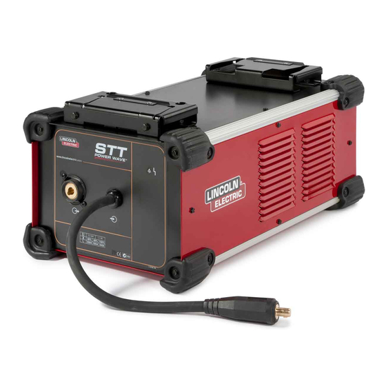
GENERAL DESCRIPTION GENERAL DESCRIPTION General Physical Description The POWER WAVE ® ® MODULE (CE) is an accessory enabling compatible power sources to perform the STT ® function without limiting the normal multi-process rating of the host machine. It is intended for use with medium range “S”– series Power Wave ®... -
Page 9: Installation
POWER WAVE ® ® MODULE (CE) INSTALLATION TECHNICAL SPECIFICATIONS - POWER WAVE MODULE (CE) (K2921-1) ® ® Module - Input Voltage and Current ® Voltage Input Amperes Notes 40Vdc Module - *Output Current Capacity ® Duty Cycle Amperes Notes 100% 750A Peak (Max.) * Defines capability of the output switch. -
Page 10: Safety Precautions
POWER WAVE ® ® MODULE (CE) INSTALLATION SAFETY PRECAUTIONS Read • Do not mount the Power Wave “S” series power source and this entire installa- STT Module combination over combustible surfaces. Where tion section before you start installation. there is a combustible surface directly under stationary or fixed electrical equipment, that surface shall be covered with ELECTRIC SHOCK can kill. -
Page 11: Connection Between Power Source And Stt Module
POWER WAVE ® ® MODULE (CE) INSTALLATION CAUTION WARNING Regarding cable placement, best results will be obtained Never reverse the polarity at the input of the STT Module (DO when control cables are routed separate from the weld NOT connect the negative stud of the power source to input cables. -
Page 12: Output Cable Guidelines
POWER WAVE ® ® MODULE (CE) INSTALLATION TABLE A.1 OUTPUT CABLE GUIDELINES Percent CABLE SIZES FOR COMBINED LENGTHS OF ELECTRODE AND WORK CABLES Duty (RUBBER COVERED COPPER - RATED 75°C)** Amperes Cycle 0 to 50 Ft. 50 to 100 Ft. 100 to 150 Ft. -
Page 13: Remote Sence Lead Connections
POWER WAVE ® ® MODULE (CE) INSTALLATION REMOTE SENSE LEAD CONNECTIONS RECOMMENDATIONS: • Position the sense leads out of the path of the weld Voltage Sensing Overview current. Especially any current paths common to adjacent The STT welding process requires the use of remote voltage ®... - Page 14 POWER WAVE ® ® MODULE (CE) INSTALLATION • For circumferential applications, connect all work leads on one side of the weld joint, and all of the work voltage sense leads on the opposite side, such that they are out of the current path. POWER SOURCE POWER...
-
Page 15: Connection Diagram System
POWER WAVE ® ® MODULE (CE) INSTALLATION CONNECTION DIAGRAM SYSTEM STT MODULE (CE) CONNECTION DIAGRAM Figure A.5 K940-XX K1543-XX ELECTRODE WORK REFER TO "OUTPUT CABLE GUIDELINES" FOR RECOMMENDED CABLE SIZE K14072-1 LF-45 K470-XX ARCLINK WORK ELECTRODE CABLE LF-45 BACK CONNECTIONS A.01 M22498... -
Page 16: Safety Precautions
The standard weld set shipped with the host power source encompasses a wide range of common processes that will meet most needs. If the STT ® modes are not available, or if a special weld mode is desired, visit www.powerwavesoftware.com or contact the local Lincoln Electric sales representative. -
Page 17: Commom Equipment Packaces
MODULE (CE) CASE FRONT CASE FRONT DESCRIPTIONS 1. Status LED – Provides ArcLink ® status of Power Wave STT Module. Note: During normal power-up, the LED will flash green up to 60 seconds as the equipment performs self tests. LED condition Definition Steady green. - Page 18 POWER WAVE ® ® MODULE (CE) OPERATION ® MODULE (CE) CASE BACK CASE BACK DESCRIPTIONS 1. ArcLink ® Pigtail – Connects directly to the ArcLink ® Out receptacle on the rear of the power source. 2. Differential I/O Pigtail – Connects directly to the Differential I/O output receptacle on the rear of the power source. 3.
-
Page 19: Maintenance
POWER WAVE ® ® MODULE (CE) MAINTENANCE SAFETY PRECAUTIONS WARNING ELECTRIC SHOCK can kill. • Disconnect input power before servicing. • Do not operate with covers removed. • Do not touch electrically live parts. • Only qualified persons should install, use or service this equipment. -
Page 20: Troubleshooting
HOW TO USE TROUBLESHOOTING GUIDE WARNING Service and Repair should only be performed by Lincoln Electric Factory Trained Personnel. Unauthorized repairs performed on this equipment may result in danger to the technician and machine operator and will invalidate your factory warranty. - Page 21 POWER WAVE ® ® MODULE (CE) TROUBLESHOOTING Observe all Safety Guidelines detailed throughout this manual MODULE FUNCTIONAL TEST ® PREPARATION • Connect the STT module to a Power Wave S350 or other compatible machine. ® (This test assumes the host power source has been calibrated.) •...
-
Page 22: Using The Status Led To Troubleshoot System Problems
POWER WAVE ® ® MODULE (CE) TROUBLESHOOTING Observe all Safety Guidelines detailed throughout this manual USING THE STATUS LED TO TROUBLESHOOT SYSTEM PROBLEMS The STT ® Module is equipped with a Status Light. If a problem occurs it is important to note the condition of the status lights. -
Page 23: Error Codes
POWER WAVE ® ® MODULE (CE) TROUBLESHOOTING Observe all Safety Guidelines detailed throughout this manual ERROR CODES FOR THE STT ® MODULE The following is a partial list of possible error codes for the STT ® MODULE. ® MODULE Error Code # Indication Thermal error Indicates over temperature. -
Page 24: On Board Led's For The Stt Switch Pc Board
POWER WAVE ® ® MODULE (CE) TROUBLESHOOTING Observe all Safety Guidelines detailed throughout this manual ON BOARD LED’S FOR THE STT SWITCH PC BOARD STT SWITCH PC BOARD MACHINE LED1 LED2 LED3 INDICATION OUTPUT (GATE) (STATUS) (+15V) ON/OFF Normal Condition – STT ®... - Page 25 POWER WAVE ® ® MODULE (CE) TROUBLESHOOTING Observe all Safety Guidelines detailed throughout this manual PROBLEMS POSSIBLE RECOMMENDED (SYMPTOMS) CAUSE COURSE OF ACTION BASIC MACHINE PROBLEMS Input fuses keep blowing 1. Improperly sized input fuses. 1. Make sure fuses are properly sized. See installation section of this manual for recommended sizes.
- Page 26 POWER WAVE ® ® MODULE (CE) TROUBLESHOOTING Observe all Safety Guidelines detailed throughout this manual PROBLEMS POSSIBLE CAUSE RECOMMENDED (SYMPTOMS) COURSE OF ACTION BASIC MACHINE PROBLEMS 1. Check for proper fan operation. (Fans Thermal error indication on STT ® Module 1.
- Page 27 POWER WAVE ® ® MODULE (CE) DIAGRAMS...
- Page 28 POWER WAVE ® ® MODULE (CE) DIAGRAMS 8.48 11.51 10.49 24.80 13.94 3.97 6.00 3.97 2.48 18.35 3.98 A.01 L15814-1...
- Page 29 POWER WAVE ® ® MODULE (CE) NOTES...
- Page 30 WARNING Do not touch electrically live parts or Keep flammable materials away. Wear eye, ear and body protection. electrode with skin or wet clothing. Insulate yourself from work and AVISO DE ground. Spanish PRECAuCION No toque las partes o los electrodos Mantenga el material combustible Protéjase los ojos, los oídos y el bajo carga con la piel o ropa moja-...
- Page 31 WARNING Keep your head out of fumes. Turn power off before servicing. Do not operate with panel open or Use ventilation or exhaust to guards off. remove fumes from breathing zone. AVISO DE Spanish PRECAuCION Los humos fuera de la zona de res- Desconectar el cable de ali- No operar con panel abierto o piración.
- Page 32 Lincoln Electric for advice or information about their use of our products. We respond to our customers based on the best information in our possession at that time. Lincoln Electric is not in a position to warrant or guarantee such advice, and assumes no liability, with respect to such information or advice.
Need help?
Do you have a question about the POWER WAVE STT and is the answer not in the manual?
Questions and answers