
Related Manuals for elero Junior 2


Summary of Contents for elero Junior 2
- Page 1 Junior 1 / Junior 1s / Junior 2 Linear actuator Operating instructions Please take care of the operating instructions! 04/2016, TN: 2010851...
- Page 2 Translation from the original German version. All other documents in different languages are translations of the original version. Subject to change without notice. All rights reserved in the event of registrati-on of patents, working models or design patents.
-
Page 3: Table Of Contents
3.3.2 Information relating to the self-locking facility ..........14 Installation ..................15 Mechanical fastening ..................16 Electrical connection..................17 Optional attachments..................18 4.3.1 Optional brake ....................18 4.3.2 Optional potentiometer ................... 18 4.3.3 Option Absolutwertgeber 0...10V ..............19 4.3.4 Optional shaft encoder ................... 21 4.3.5 Optional rotary pulse encoder elero ............... 22... - Page 4 Table of contents 4.3.6 Optional motor control board (MSP) ............... 23 4.3.7 Bellows option ....................24 Limit switches ....................24 4.4.1 Permissible adjusting range of limit switches ..........25 4.4.2 Adjustment of limit switches ................25 4.4.3 Operation of unit ..................... 27 General dimension drawing ................
-
Page 5: General
General General Information relating to the installation instructions The classification of the contents is based on the life stages of the linear drive (here- inafter referred to as the “device”). The manufacturer reserves the right to make changes to the technical specifications stated in these installation instructions. In detail these can differ from the respective version of the device without the factual information being fundamentally changed and without losing their validity. The cur- rent status of the technical specifications can be requested from the manufacturer at any time. Any claims arising from this cannot be asserted. Deviations from the text and pictorial statements are possible and are dependent on the technical develop- ment, equipment and accessories of the device. -
Page 6: Foreseeable Misuse
General If a direct or indirect hazard to personnel cannot be ruled out, additional meas- ures (e.g. covers, barriers, etc.) must be taken in order to minimise the potential risk accordingly. The operator alone is liable for any damage arising from the non-intended use of the device. The manufacturer assumes no liability for personal injury or dam- age to property caused through misuse or procedural errors, improper operator control or improper start of operation. The device must be operated only by trained and authorized skilled personnel subject to compliance with all safety notices and directions. -
Page 7: Customer Service Of The Manufacturer
Customer service of the manufacturer The device may be repaired only by the manufacturer in the event of a fault. The address for sending in the device to the customer service department can be found on the inside of the back cover. If you have not purchased the device directly from elero, please contact the manufacturer of the machine or the supplier of the device. Mechanically secure the machine before dismantling the device. The device must not be separated from the machine by force. -
Page 8: Safety
Safety Safety General safety notices and directions These installation instructions contain all the safety notices and directions that must be observed in order to avoid and prevent dangers when working with the device in the individual life cycles. Safe use of the device is guaranteed when all the specified safety notices and directions are complied with. 2.1.1 Formulation of the safety notices and directions The safety notices and directions in this document are marked with safety sym- bols and formulated in accordance with the SAFE principle. They contain speci- fications relating to the type and source of danger, the possible consequences, as well as the prevention of the danger. The following table defines the representation and description of the levels of danger with possible physical injury, as used in these installation instructions. - Page 9 Safety The following table describes the symbols used in these installation instructions for the graphic display of danger situations in connection with the symbol for the danger level. Symbol Meaning Danger due to an electrical voltage, electric shock: This symbol refers to dangers associated with electrical currents. Danger of crushing and killing people: This symbol refers to dangers due to which the entire body or individual limbs can become crushed or injured. The following table defines the representation and description used in the instal- lation instructions for situations in which damage can occur to the product or draws attention to important facts, statuses, tips and information.
-
Page 10: Safety Principles
Safety Safety principles The device is built according to state-of-the-art technology and the generally accepted rules of safety and it is safe to operate. The basic safety and health requirements of the applicable laws, standards, directives and guidelines have been applied in the construction of the device. The safety of the device is con- firmed by the Declaration of Incorporation. All specifications pertaining to safety relate to the currently valid regulations of the European Union. In other countries it must be ensured by the plant operator that the applicable laws and national regulations are complied with. In addition to the safety notices and directions in these installation instructions, the generally applicable regulations regarding accident prevention and environ- mental protection must be observed and complied with. The device must only be used when in perfect working order, for its intended use, and in compliance with the safety notices and directions in these installa- tion instructions. -
Page 11: General Duties Of The Plant Operator
Safety General duties of the plant operator The plant operator is obligated to use the device only in perfect and opera- tionally safe condition. He must ensure that, in addition to the safety notices and directions in the installation instructions, the generally accepted safety and accident prevention regulations, the specifications of DIN VDE 0100 and the provisions relating to environmental protection of the respective country of use, are heeded and complied with. The plant operator is responsible that all work with the device is performed only by trained, safety instructed and authorized personnel. Ultimately responsible for accident-free operation is the plant operator of the device or the personnel authorized by the plant operator. The plant operator is responsible for compliance with the technical specifi- cations, in particular for compliance with the static loads. Non-compliance with the static loads may cause loss of the support or holding function. -
Page 12: Safety Notices And Directions Relating To The Technical Condition
Safety Safety notices and directions relating to the technical condi- tion The device must be checked before installation for damage and proper condition. The plant operator is obligated to operate the device only in perfect and operationally safe condition. The technical condition must comply with the legal requirements at all times. If dangers to personnel or changes in operating behaviour are recognized, the device must be shut down immediately and the incident reported to your superiors or to the plant operator. -
Page 13: Safety Instructions Relating To Operation
Safety Safety instructions relating to operation The operator of the device is obligated to ensure the safe and proper state of the device before the initial start of operation. This is also necessary during operation of the device at regular intervals to be determined by the plant operator. In the event of a fault, misuse and/or if control components are not con- nected correctly, this can cause the supporting and retaining function of the device to be impaired. -
Page 14: Product Description
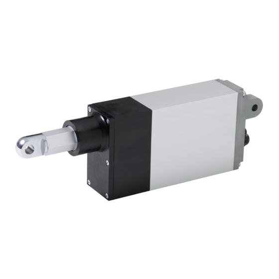
Product description Product description General The device is an electromechanical linear drive. It performs linear movements. Fig. 1 Components of the device Options (e.g. potentiometer or rotary pulse encoder) Fastening on piston side Fastening on housing side Limit switch adjusting screws Electrical connection Housing cover Product variants The device can be obtained in various configurations. -
Page 15: Technical Specifications
Product description Technical specifications All information in this section relates to an ambient temperature of 20°C. 3.3.1 Summary of the technical parameters Technical specifications Junior 1 Junior 1s Junior 2 Rated voltage 24 V DC Rated current up to 1.2 A up to 2.5 A... -
Page 16: Information Relating To The Self-Locking Facility
Product description 3.3.2 Information relating to the self-locking facility WARNING Danger of injury through loss of the self-locking facility. Crushing and fatal injuries are possible. • Use device with a brake. CAUTION Possible damage to the device or customer’s machine through loss of the self- locking facility. • Use device with a brake. With the devices it is differentiated between dynamic and static self-locking. Dy- namic self-locking arises from movement and static self-locking when the device is at a standstill. The self locking facility on the devices is dependent on various... -
Page 17: Installation
Installation Installation WARNING Danger of injury due to weathering influences. The skin may suffer frostbite or burns. • Wear personal protective equipment. WARNING Danger of injury due to incorrectly dimensioned mountings. Crushing and fatal injuries are possible. • U se only fastening materials that are suitable for the dimensions of the mountings. • T he counter-mountings (provided by customer) must be rated at least for the forces for which the device was designed. WARNING Danger of injury through loss of the support and holding function. Crushing and fatal injuries are possible. • Pay attention to static loads. -
Page 18: Mechanical Fastening
Installation CAUTION Damage to the device due to the connecting rod jamming. • The linear path of the piston must be freely moveable at all times. • The pivoting range of the device must be kept free. CAUTION Damage to the device due to loss of the support and holding function. • Pay attention to static loads. CAUTION Damage to device through direct reversal of polarity of stroke direction. -
Page 19: Electrical Connection
Installation Electrical connection WARNING Danger of life-threatening injury due to faulty electrical connection. Electric shock possible. • Prior to commissioning, check the type and value of connection voltage. • For devices with rated voltage 230 V 1 AC, 50 Hz, the correct connection of the PE conductor must be checked prior to commissioning. CAUTION Damage to unit for versions with rated voltage 230 V 1 AC, 50 Hz caused by faulty electrical connection. -
Page 20: Optional Attachments
Installation Please refer to the following pages or the circuit diagram enclosed with the delivery for connection of the option selected by you. Optional attachments 4.3.1 Optional brake CAUTION Damage to the device due to incorrect connection of the brake. • Operate the device only when the brake is released. • Do not tap the brake voltage parallel to the motor. With the integrated brake you can decelerate the stroke movement of the con- necting rod faster and optimize the static safety. -
Page 21: Option Absolutwertgeber 0
Installation 4.3.3 Optional absolute encoder 0...10 V The integrated absolute encoder supplies information about the position of the connecting rod. The encoder is a contact-free absolute multiturn measuring system. As soon as voltage is applied to the encoder it sends a secure voltage signal that corresponds with the position of the connecting rod. An output of 0 - 10 V for entire length of the stroke is standard. - Page 22 Installation Connection configuration Signal 0 - 10 V Conductor number Conductor colour Tab. 3 Connection assignment of the absolute encoder Principle circuit output Fig. 2 Principle circuit output...
-
Page 23: Optional Shaft Encoder
Installation 4.3.4 Optional shaft encoder The integrated shaft encoder supplies information about the movement of the connecting rod. Please refer to the following table for the parameters necessary for operation. Electrical parameters Output switching Push-pull Rated voltage (U 5 – 24 V DC Current consumption (no load) max. 30 mA Permissible load per channel max. -
Page 24: Optional Rotary Pulse Encoder Elero
Installation 4.3.5 Optional rotary pulse encoder elero The integrated shaft encoder supplies information about the movement of the connecting rod. Please refer to the following table for the parameters necessary for operation. Electrical parameters Output switching Push-pull Rated voltage (U 5 – 30 V DC Current consumption (no load) max. 30 mA Permissible load per channel max. -
Page 25: Optional Motor Control Board (Msp)
Installation 4.3.6 Optional motor control board (MSP) Pinout of plugs: All voltage connections are protected against polarity reversal. The drive hous- ing is not provided with earthing. The signal inputs are galvanically isolated from the supply voltage. The drive is designed for a fixed connection to a direct volt- age source. 3-pin plug (large): 1 – GND (ground/earth) 2 – Vss (supply voltage) – Housing 4-pin plug (small): 1 – I (input, direction of travel signal "Moved out") 2 – I (input, direction of travel signal "Moved in") 3 –... -
Page 26: Bellows Option
Installation Functions that can be activated: Function Motor is de-energised and not short-circuited Motor is de-energised and not short-circuited Motor is de-energised and not short-circuited Motor is de-energised and not short-circuited Motor is short-circuited (fast stop) Piston rod moves out Piston rod moves in Motor is de-energised and not short-circuited Tab. -
Page 27: Permissible Adjusting Range Of Limit Switches
Installation 4.4.1 Permissible adjusting range of limit switches CAUTION Risk of damage to unit by exceeding permissible range of adjustment. • T he "retracted" and "ejected" limit switches must not be adjusted any more than 10 mm in the direction of stroke reduction. Fig. 3 Permissible adjusting range End position "Moved out" End position "Moved in" 4.4.2 Adjustment of limit switches CAUTION Risk of damage to unit by incorrect limit switch adjustment. - Page 28 Installation The adjusting screws are in the end cover on the housing side. Carefully remove the locking frame (not applicable if "Rotary knob" option is used). Move the piston rod a few centimetres away from the targeted limit switch position. Adjust the limit switch (+/-).(see Tab. 8 "Setting for adjusting screw 1" and Tab. 9 "Setting for adjusting screw 2"). Move the drive back to the limit switch. Repeat the process until the desired dimension is reached.
-
Page 29: Operation Of Unit
Installation Adjustment of limit switch "ejected" (setting screw 1) Stroke reduction: Turn in direction of "–" Limit switch position is moved MINUS in direction of "retracted". (Piston rod ejects less no- tably) Stroke reduction: Turn in direction of "+" Limit switch position is moved PLUS in direction of "ejected". -
Page 30: General Dimension Drawing
Installation General dimension drawing On account of the multitude of configuration possibilities no dimensions sheets are listed below. You can request from the manufacturer an exact dimensions sheet for the de- vice supplied, if required. -
Page 31: Declaration Of Incorporation
Declaration of incorporation Declaration of incorporation The complete declaration of incorporation can be downloaded from our website: www.elero-linear.de/downloads. -
Page 32: Waste Disposal
Waste disposal Waste disposal Scrapping When scrapping the device, comply with the internationally, nationally and re- gionally specific laws and regulations valid at that point in time. Ensure that the recycling capability, dismantling capability and separation capa- bility of the materials and subassemblies as well as the environmental and health dangers are all taken into consideration for the recycling and waste dis- posal. Material groups, such as plastics and metals of different types, must be sorted before submitting to the recycling and waste disposal process. Disposal of waste electrical and electronic components The disposal and recycling of waste electrical and electronic components must take place in compliance with the relevant laws and national regulations.
Need help?
Do you have a question about the Junior 2 and is the answer not in the manual?
Questions and answers