
Related Manuals for Fronius Artis 210


Summary of Contents for Fronius Artis 210
- Page 1 Operating Instructions Artis 170 Artis 210 EN-US Operating instructions 42,0426,0516,EA 001-13112023...
-
Page 3: Table Of Contents
Table of contents Safety Instructions Explanation of Safety Instructions General Intended Use Environmental Conditions Obligations of the Operating Company Obligations of Personnel Grid Connection Residual current circuit breaker Personal Protection and Protection of Others Data on noise emission values Danger from toxic gases and vapors Danger from Flying Sparks Risks from mains current and welding current Stray welding currents... - Page 4 Connecting the Mains Cable General Safety Connecting the mains cable Commissioning Safety General Connecting the Gas Cylinder Connecting the welding torch to the welding system Establishing a Ground Earth Connection with the Workpiece Measuring the welding circuit resistance "r" Welding Mode TIG Operating Modes Safety Symbols and explanations...
- Page 5 Average consumption values during welding Average shielding gas consumption during TIG welding Technical data Special Voltage Artis 170 EF, Artis 170 np Artis 170 MV/B, Artis 170 MV/np Artis 210 EF, Artis 210 np Artis 210 MV/B, Artis 210 MV/np...
-
Page 6: Safety Instructions
Safety Instructions Explanation of DANGER! Safety Instruc- tions Indicates an immediate danger. ▶ Death or serious injury may result if appropriate precautions are not taken. WARNING! Indicates a possibly dangerous situation. ▶ Death or serious injury may result if appropriate precautions are not taken. CAUTION! Indicates a situation where damage or injury could occur. -
Page 7: Intended Use
Intended Use The device is to be used exclusively for its intended purpose. The device is intended exclusively for the welding process specified on the rating plate. Utilization for any other purpose, or in any other manner, shall be deemed to be "not in accordance with the intended purpose."... -
Page 8: Grid Connection
Grid Connection Devices with a high output can influence the energy quality of the grid due to their current consumption. This may affect a number of device types in terms of: connection restrictions criteria regarding maximum permissible grid impedance criteria regarding the minimum required short-circuit power both at the interface with the public grid See technical data In this case, the operator or the person using the device should check whether or... -
Page 9: Data On Noise Emission Values
Data on noise The device produces a maximum noise level of <80 dB(A) (ref. 1pW) when idling emission values and in the cooling phase following operation in relation to the maximum permit- ted operating point at standard loading in accordance with EN 60974-1. A workplace-specific emission value for welding (and cutting) cannot be spe- cified because this value depends on the welding process and the environmental conditions. -
Page 10: Risks From Mains Current And Welding Current
Keep suitable, tested fire extinguishers on hand. Sparks and pieces of hot metal may also get into surrounding areas through small cracks and openings. Take appropriate measures to ensure that there is no risk of injury or fire. Do not undertake welding in areas at risk of fire and explosion, or on sealed tanks, drums, or pipes if these have not been prepared in accordance with cor- responding national and international standards. -
Page 11: Stray Welding Currents
When working at elevated heights, wear a safety harness to prevent falls. Before working on the device, switch off the device and remove the mains plug. Secure the device to prevent the mains plug from being connected and switched on again by applying a clearly legible and understandable warning sign. After opening the device: Discharge all electrically charged components Ensure that all components are disconnected from the power supply... -
Page 12: Emf Measures
Test and assess the immunity of equipment in the vicinity of the device in ac- cordance with national and international provisions. Examples of interference- prone equipment that could be affected by the device: Safety devices Grid power lines, signal lines, and data transfer lines IT and telecommunications equipment Devices for measuring and calibrating Supporting measures to avoid EMC problems:... -
Page 13: Requirement For The Shielding Gas
Slag may fly off cooling workpieces. Therefore, also wear regulation-compliant protective equipment when reworking workpieces and ensure that other persons are sufficiently protected. Leave the welding torch and other parts with a high operating temperature to cool before working on them. Special regulations apply in areas at risk of fire or explosion –... -
Page 14: Danger Posed By Shielding Gas Leak
Never hang a welding torch on a shielding gas cylinder. Never touch a shielding gas cylinder with an electrode. Risk of explosion: Never weld on a compressed shielding gas cylinder. Always use suitable shielding gas cylinders for the application in question and the correct matching accessories (controller, hoses, and fittings, etc.) Only use shielding gas cylinders and accessories that are in good condition. -
Page 15: Safety Measures In Normal Operation
It is essential to conduct a visual inspection of the device to check for damage after it has been transported but before commissioning. Have any damage re- paired by trained service technicians before commissioning the device. Safety Measures Only operate the device when all safety devices are fully functional. If the safety in Normal Oper- devices are not fully functional, there is a danger of: ation... -
Page 16: Safety Inspection
Copyright Copyright of these Operating Instructions remains with the manufacturer. Text and illustrations were accurate at the time of printing. Fronius reserves the right to make changes. The contents of the Operating Instructions shall not provide the basis for any claims whatsoever on the part of the purchaser. If you... - Page 17 have any suggestions for improvement, or can point out any mistakes that you have found in the Operating Instructions, we will be most grateful for your com- ments.
-
Page 19: General Information
General information... -
Page 21: General
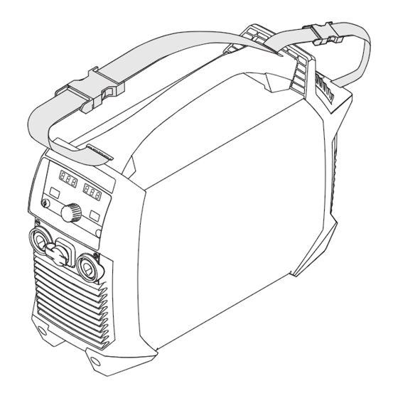
General Device concept The Artis 170 and Artis 210 TIG weld- ing systems are microprocessor-con- trolled inverter power sources. A modular design and easy ability to extend the system guarantee a high degree of flexibility. The welding systems are generator-... -
Page 22: Remote Control Operating Mode
Remote control The Artis 170 and Artis 210 welding systems can be operated using the following operating mode remote controls: RC Bar 1P RC Panel MMA RC Pedal TIG RC Panel Basic TIG Warning notices Warning notices and safety symbols can be found on welding systems with the on the device CSA test mark for use in the North American region (USA and Canada). - Page 23 Safety symbols on the rating plate: Welding is dangerous. The following basic requirements must be met: Adequate welding qualifications Appropriate protective equipment Exclusion of unauthorized persons Do not use the functions described here until you have fully read and understood the following documents: These Operating Instructions All system component Operating Instructions, especially the safety rules...
-
Page 25: Operating Controls And Connections
Operating controls and connec- tions... -
Page 27: Control Panel
Control Panel General NOTE! Because of software updates, certain functions may be available for your device but not described in these Operating Instructions or vice versa. In addition, individual figures may also differ slightly from the operating ele- ments of your device. These operating elements function in exactly the same way, however. - Page 28 HF ignition indicator (high frequency ignition) Illuminates when the "IGn" setup parameter has been set to "on" Tacking indicator Illuminates when the "tAC" setup parameter has been set to a period of time Pulsing indicator Illuminates when the "F-P" setup parameter has been set to a pulse fre- quency Spot welding indicator Illuminates when the "SPt"...
- Page 29 Starting current I Welding current I Lowering current I Final current I Before the start of welding, the left digital display shows the set value. For , and I , the right digital display also indicates the % amount of the welding current I After the start of welding, the left digital display shows the current actual value of the welding current.
- Page 30 % indicator Illuminates when parameters "I ", "I ", and "I " have been selected, as well as the setup parameters "dcY", "I‑G", and "HCU" mm indicator Illuminates when the "ELd" setup parameter is set "Mode" button For selecting the operating mode 2-step mode 4-step mode MMA welding...
- Page 31 For TIG welding UpSlope t Period of time it takes to rise from the starting current I to the specified main current I during TIG welding t-u for the UpSlope is displayed on the left digital display. IMPORTANT! The UpSlope t is saved separately for the following operating modes: 2-step mode...
-
Page 32: Connections, Switches, And Mechanical Components
Connections, Switches, and Mechanical Compon- ents Operating Con- trols, Connec- tions, and Mech- anical Compon- ents Artis 170/210 (10) Artis 170/210 Control panel (-) Current socket with integrated gas connection For connecting: the TIG welding torch the electrode cable during manual metal arc welding... -
Page 33: Installation And Startup
Installation and Startup... -
Page 35: Minimum Equipment For Welding Operations
Minimum equipment for welding operations General Depending on the welding process, a minimum level of equipment is required to work with the welding system. The following describes the welding processes and the corresponding minimum equipment for welding operations. TIG DC welding Welding system Return lead cable TIG welding torch with or without rocker switch... -
Page 36: Before Installation And Initial Operation
Before installation and initial operation Safety WARNING! Danger from incorrect operation and work that is not carried out properly. This can result in serious personal injury and damage to property. ▶ All the work and functions described in this document must only be carried out by technically trained and qualified personnel. -
Page 37: Generator-Powered Operation
CAUTION! Danger due inadequately dimensioned electrical installations. This can lead to serious damage ▶ The grid lead and its fuse protection should be designed to suit the existing power supply. The technical data on the rating plate should be followed. Generator- The welding system is generator-compatible. -
Page 38: Connecting The Mains Cable
Connecting the Mains Cable General If a welding system is delivered without a mains cable installed, a mains cable corresponding to the welding system's connection voltage must be connected before commissioning. The mains cable is included in the scope of supply for the welding system. Safety WARNING! Danger from incorrect operation and work that is not carried out properly. -
Page 39: Commissioning
Commissioning Safety WARNING! Danger from electrical current. This can result in serious personal injury and damage to property. ▶ Before starting work, switch off all devices and components involved, and disconnect them from the grid. ▶ Secure all devices and components involved so they cannot be switched back ▶... -
Page 40: Connecting The Welding Torch To The Welding System
max. 5 bar (72 psi) Connecting the NOTE! welding torch to the welding sys- Do not use pure tungsten electrodes for Artis welding systems (color code: green). Fit parts to the welding torch according to the Operating Instructions for the welding torch Artis Artis MV... -
Page 41: Establishing A Ground Earth Connection With The Workpiece
Establishing a Ground Earth Connection with the Workpiece Measuring the IMPORTANT! For optimum welding results, determine the welding circuit resist- welding circuit ance " r " before starting welding. resistance "r" The welding circuit resistance " r " must also be determined if one of the follow- ing components of the welding system is changed: Torch hosepack Welding torch... -
Page 43: Welding Mode
Welding Mode... -
Page 45: Tig Operating Modes
TIG Operating Modes Safety WARNING! Danger due to incorrect operation. This can result in severe personal injury and damage to property. ▶ Do not use the functions described here until you have fully read and under- stood the Operating Instructions. ▶... -
Page 46: Symbols And Explanations
Symbols and ex- planations Pull back and hold the torch trigger | Release the torch trigger | Briefly pull back the torch trigger (< 0.5 s) Push the torch trigger forward and hold | Release the torch trigger Starting-current phase: the temperature is raised gently at low welding current, so that the filler metal can be positioned correctly Starting current duration UpSlope phase: steady rise of the starting current to the main current... -
Page 47: 2-Step Mode
2-Step Mode Welding: Pull back the torch trigger and hold it in this position End of welding: Release the torch trigger down 2-step mode The Setup menu can be used to set a starting current time (t-S) and a final cur- rent time (t-E) for 2-step mode. -
Page 48: Spot Welding
Spot Welding If a value has been set for the setup parameter SPt, then 2-step mode operating mode is the same as spot welding operating mode. The spot welding special dis- play illuminates on the control panel. Welding: Briefly pull back the torch trigger The duration of welding corresponds to the value that was entered for the setup parameter SPt. -
Page 49: Tig Welding
TIG welding Safety WARNING! Danger from incorrect operation and work that is not carried out properly. This can result in serious personal injury and damage to property. ▶ All the work and functions described in this document must only be carried out by technically trained and qualified personnel. -
Page 50: Tig Welding
TIG welding Select the desired TIG operating mode by pressing the operating mode but- ton: Press the dial In the welding parameter overview, the assigned welding parameters illumin- ate to around 50%. The segment of the currently selected welding parameter illuminates fully. -
Page 51: Welding Parameters
2-step mode 4-step mode When the "Trigger" setup parameter is set to "oFF" When a foot-operated remote control has been connected Main current 10 – 170 A ... Artis 170 10 – 210 A ... Artis 210 Factory setting: 100 A... - Page 52 Lowering current (only in 4-step mode) 1 - 200% (of the main current I Factory setting: 50% DownSlope down off / 0.01 - 9.9 s Factory setting: 1.0 s IMPORTANT! The DownSlope t is saved separately for the following down operating modes: 2-step mode 4-step mode...
-
Page 53: Igniting The Arc
Risk of injury due to an electric shock (HF ignition) Although Fronius devices comply with all the relevant standards, high frequency ignition can transmit a harmless but noticeable electric shock under certain cir- cumstances. ▶ Use prescribed protective clothing, especially gloves! ▶... -
Page 54: Contact Ignition For Welding Torch With Torch Trigger
Increase the tilt angle of the weld- ing torch and press the torch trig- ger according to the selected oper- ating mode The arc ignites without coming into contact with the workpiece. Tilt the welding torch to the nor- mal position Carry out welding Contact ignition When the setup parameter IGn is set to OFF, the HF ignition is deactivated. - Page 55 Press the torch trigger Shielding gas flows Gradually tilt the welding torch up until the tungsten electrode touches the workpiece Raise the welding torch and rotate it into its normal position The arc ignites. Carry out welding...
-
Page 56: Contact Ignition For Welding Torch Without Torch Trigger
Contact ignition When the setup parameter "IGn" is set to "oFF", the HF ignition is deactivated. for welding torch The arc ignites when the workpiece makes contact with the tungsten electrode. without torch trigger The setup parameter "Tri" must be set to "oFF". Procedure for igniting the arc using contact ignition for welding torches without torch trigger: Position the gas nozzle at the igni-... -
Page 57: Igniting The Arc Using High-Frequency Contact(Touch-Hf)
Risk of injury due to an electric shock (Touch-HF) Although Fronius devices comply with all relevant standards, the high-frequency ignition can transmit a harmless but noticeable electric shock under certain cir- cumstances. ▶ Use prescribed protective clothing, especially gloves! ▶... -
Page 58: Special Functions
Special functions Arc break monit- If the arc breaks and no current flow takes place during the time set in the Setup oring function menu, the welding system automatically switches off. The control panel displays the service code "no | Arc". Press any button on the control panel or the torch trigger to restart the welding process. -
Page 59: Tacking Function
TIG pulsing in operation: 1/F-P down TIG pulsing - welding current progression curve Key: Starting current Pulse frequency *) Duty cycle Final current Base current UpSlope Main current DownSlope Down *) (1/F-P = Time between two impulses) Tacking function There is a tacking function on the welding system. When a period of time is set for the setup parameter tAC (tacking), the tacking function is assigned to the 2-step and 4-step modes. - Page 60 Duration of pulsed welding current for tacking process Starting current Final current UpSlope DownSlope Down Main current IMPORTANT! When using a pulsed welding current: The welding system automatically regulates the pulse parameters in relation to the set main current I No pulse parameters have to be set.
-
Page 61: Manual Metal Arc Welding
Manual Metal Arc Welding Safety WARNING! Danger from incorrect operation and work that is not carried out properly. This can result in serious personal injury and damage to property. ▶ All the work and functions described in this document must only be carried out by technically trained and qualified personnel. -
Page 62: Mma Welding
MMA welding Select the manual metal arc welding operating mode by pressing the operat- ing mode button: IMPORTANT! If the manual metal arc welding operating mode is selected, the welding voltage is only available after a delay of 3 seconds. Turn the dial to set the welding current The set value is immediately applied. - Page 63 NOTE! The welding system regulates the duty cycle parameter "dcY" and the base cur- rent "I-G" according to the set pulse frequency. 1/F-P Pulse welding - welding current curve Adjustable parameters: Pulse frequency (1/F-P = Time between two pulses) SoftStart / HotStart Fixed parameters: Base current Duty cycle...
-
Page 64: Starting Current > 100% (Hotstart)
Starting current Advantages > 100% (Hot- Improved ignition properties, even when using electrodes with poor ignition Start) properties Better fusion of base material in the start phase, therefore less neutraliza- tion Slag inclusions largely avoided Key: I (A) Hot current time, 0-2 s, Factory setting 0.5 s HotStart current,... -
Page 65: Anti-Stick Function
Anti-stick func- As the arc becomes shorter, the welding voltage may also fall so that the stick tion electrode is more likely to stick to the workpiece. This may also cause the stick electrode to burn out. Electrode burn-out is prevented by activating the anti-stick function. If the stick electrode begins to stick, the welding system immediately switches the welding current off. -
Page 67: Setup Settings
Setup Settings... -
Page 69: The Setup Menu
The Setup Menu General The welding system Setup menu provides easy access to expert knowledge and additional functions. The Setup menu makes it possible to easily adjust the para- meters for various tasks. Located in the Setup menu are: Setup parameters with a direct effect on the welding process Setup parameters for pre-setting the welding system Accessing the Setup Menu... -
Page 70: Adjusting Parameters
Adjusting Para- The parameters in the Setup menu are adjusted as follows: meters Turn the selection dial and select the desired setup parameter Press selection dial to adjust the value for the setup parameter The parameter is displayed on the left digital display. The currently set value for the parameter is displayed on the right digital display. -
Page 71: Tig Setup Menu
TIG Setup Menu Parameters in The following parameters are available through the TIG Setup menu: the TIG Setup menu Electrode diameter 0.0 - 3.2 mm Factory setting: 2.4 mm Spot welding time/stitch welding time off / 0.05 - 25 s Factory setting: off If a value has been set for the setup parameter SPt, this means that 2-step mode corresponds to the spot welding mode. - Page 72 Tacking function is switched off The tacking special indicator illuminates on the control panel if a value has been set. Pulse frequency off / 0.2 - 990 Hz Factory setting: off The set pulse frequency is also applied for the lowering current. The pulsing special indicator illuminates on the control panel if a value for the pulse frequency has been entered.
- Page 73 Final current time The final current time indicates the duration of the final-current phase. off / 0.01 - 9.9 s Factory setting: off IMPORTANT! The final current time is only valid for 2-step mode and spot weld- ing. In 4-step mode, the duration of the final-current phase is determined by the torch trigger (section "TIG operating modes").
-
Page 74: Parameters In The Tig - 2Nd Level Setup Menu
ALL: All operating modes are reset. Left display Right display TIG - 2nd level Setup menu For setting the following parameters: r (welding circuit resistance) Slope Time 1 (only in 4-step mode) Slope Time 2 (only in 4-step mode) Trigger HF ignition Pulse TAC display Ignition Time-Out... - Page 75 Pressing the torch trigger or the gas-test button restarts the determination of the welding circuit resistance. In the event of an error: Inspect torch hosepack, welding torch, and return lead cable for damage Check connections and contacts Check the cleanliness of the workpiece surface Slope Time 1 (only available in 4-step mode) Ramping time from the main current I to the lowering current I...
- Page 76 "on". CAUTION! Risk of injury due to an electric shock Although Fronius devices comply with all the relevant standards, high frequency ignition can transmit a harmless but noticeable electric shock under certain cir- cumstances. ▶...
- Page 77 Arc break monitoring Period of time until the safety cut-out following an arc break 0.1 - 9.9 s Factory setting: 1.0 s IMPORTANT! Arc break monitoring is a safety function and cannot be deactiv- ated. A description of the arc break monitoring function can be found in the "TIG welding"...
-
Page 78: Parameters In The 2Nd Level Setup Menu
Lift the welding torch from the workpiece Break voltage For setting a voltage value at which the welding process may be ended by slightly raising the TIG welding torch. The higher the break voltage value, the higher the arc can be raised. The break voltage values for 2-step mode, 4-step mode, and operation with a foot-operated remote control are all stored together. - Page 79 At 230 V: 10, 13, 16 A / off * At 120 V: 15, 16, 20 A * / off * * Only on Artis 170 MV / Artis 210 MV Factory setting: 16 A at a mains voltage of 230 V...
- Page 80 Only on Artis 170 MV / Artis 210 MV Depending on the trigger characteristics of the automatic circuit breaker used, the full duty cycle of 40% may not be reached with a 120 V grid (for example, USA circuit breaker type CH 15% D.C.).
-
Page 81: Rod Electrode Setup Menu
Rod Electrode Setup Menu Parameters in The following parameters are available through the stick electrode Setup menu: the stick elec- trode Setup menu HotStart current 1 - 200% Factory setting: 130% Starting current duration 0.1 - 2.0 s Factory setting: 0.5 s Start ramp To activate/deactivate the start ramp for the manual metal arc welding ignition process... - Page 82 As the arc becomes shorter, the welding voltage may also fall so that the stick electrode is more likely to stick to the workpiece. This may also cause the stick electrode to burn out. Electrode burn-out is prevented by activating the anti-stick function. If the stick electrode begins to stick, the welding system immediately switches the welding current off.
- Page 83 Reset welding system No / YES / ALL Factory setting: No YES: Only the currently active welding mode is reset (2T / 4T / trigger = oFF / STICK / STICK CEL / foot-operated remote control) ALL: All operating modes are reset. 2nd level Setup menu For viewing "system active time", "system on time", "fuse"...
-
Page 85: Troubleshooting And Maintenance
Troubleshooting and Maintenance... -
Page 87: Troubleshooting
Troubleshooting General The welding system is equipped with an intelligent safety system, which com- pletely negates the need for fuses. After correcting a possible error, the welding system can be properly operated again without having to change any fuses. Safety WARNING! Danger from incorrect operation and work that is not carried out properly. -
Page 88: Service Messages
Service mes- If "Err" is displayed on the left display and an error code is displayed on the right sages display, this is an internal service code for the welding system. Example: There can be multiple error codes. These appear by turning the dial. Take note of all displayed error codes as well as the serial number and configura- tion of the welding system, and then contact the service center with a detailed error description. -
Page 89: No Function
Err | 20 Cause: Improper use of the device Remedy: Only use the device in accordance with the intended purpose Err | 22 Cause: Welding current set too high Remedy: Ensure that the welding system is being operated at the correct mains voltage;... -
Page 90: Inadequate Function
No welding current Switch on device, display illuminates for selected process, overtemperature dis- play illuminates Cause: Duty cycle exceeded - device overloaded - fan running Remedy: Observe duty cycle Cause: Thermal automatic circuit breaker has shut down the device Remedy: Wait for device to cool down (do not switch off the device - the fan will cool the device);... - Page 91 Poor-quality weld property (strong spattering) Cause: Incorrect polarity of the electrode Remedy: Reverse the polarity of the electrode (observe manufacturer guidelines) Cause: Poor ground earth connection Remedy: Attach earthing clamps directly to the workpiece Cause: Non-viable setup setting for the selected process Remedy: Optimize the setting for the selected process in the Setup menu Tungsten electrode melts...
-
Page 92: Service, Maintenance And Disposal
Service, maintenance and disposal General The welding system only requires a minimum of service and maintenance under normal operating conditions. However, several points must be observed in order for the welding system to remain operational for years to come. Safety WARNING! Danger from electrical current. -
Page 93: Maintenance Every Two Months
Maintenance Clean air filter: every two months Disposal Disposal must only be carried out in accordance with the section of the same name in the "Safety rules" chapter. -
Page 95: Appendix
Appendix... -
Page 97: Average Consumption Values During Welding
Average consumption values during welding Average shield- Gas nozzle size ing gas con- Average con- sumption during 6 l/min 8 l/min 12 l/min 12 l/min 15 l/min sumption l/min TIG welding... -
Page 98: Technical Data
Technical data Special Voltage For devices designed for special voltages, the technical data on the rating plate applies. Artis 170 EF, Mains voltage U 1 x 230 V Artis 170 np Max. effective primary current (I 11.3 A 1eff Max. primary current (I 15.0 A... - Page 99 Insulation class EMC emission class (according to EN/IEC 60974-10) Overvoltage category Pollution degree according to IEC60664 Ambient temperature -10 °C - +40 °C / +14 °F - +104 °F Storage temperature -25 °C - +55 °C / -13 °F - +131 °F Dimensions l x w x h 435 x 160 x 310 mm / 17.1 x 6.3 x 12.2 Weight...
-
Page 100: Artis 170 Mv/B, Artis 170 Mv/Np
Artis 170 MV/B, Mains voltage 1 x 120 V / 1 x 230 V Artis 170 MV/np Max. effective primary current (I 1eff 1 x 120 V 14.5 A 1 x 230 V 11.3 A Max. primary current (I 1max 1 x 120 V 22.7 A... - Page 101 Stick electrode / 1 x 230 V 40% D.C. / 150 A 60% D.C. / 120 A 100% D.C. / 110 A Open circuit voltage (pulsed) 35 V 101 V Working voltage TIG / 1 x 120 V 10.1 - 15.6 V TIG / 1 x 230 V 10.5 - 16.8 V Stick electrode / 1 x 120 V...
-
Page 102: Artis 210 Ef, Artis 210 Np
Artis 210 EF, Mains voltage U 1 x 230 V Artis 210 np Max. effective primary current (I 13.5 A 1eff Max. primary current (I 20.0 A 1max Mains voltage tolerance -30% / +15% Mains frequency 50/60 Hz Mains fuse 16 A slow-blow Mains connection at PCC... - Page 103 Ambient temperature -10 °C - +40 °C / +14 °F - +104 °F Storage temperature -25 °C - +55 °C / -13 °F - +131 °F Dimensions l x w x h 435 x 160 x 310 mm / 17.1 x 6.3 x 12.2 Weight 9.8 kg / 21.61 lb.
-
Page 104: Artis 210 Mv/B, Artis 210 Mv/Np
Artis 210 MV/B, Mains voltage 1 x 120 V / 1 x 230 V Artis 210 MV/np Max. effective primary current (I 1eff 1 x 120 V 18.0 A 1 x 230 V 13.5 A Max. primary current (I 1max 1 x 120 V 29.0 A 1 x 230 V... -
Page 105: Explanation Of Footnotes
Stick electrode / 1 x 230 V 40% D.C. / 180 A 60% D.C. / 150 A 100% D.C. / 120 A Open circuit voltage (pulsed) 35 V 101 V Working voltage TIG / 1 x 120 V 10.1 - 16.8 V TIG / 1 x 230 V 10.1 - 18.4 V Stick electrode / 1 x 120 V... - Page 106 On a public grid with 230 V and 50 Hz D.C. = duty cycle PCC = interface to the public grid...
-
Page 107: Overview With Critical Raw Materials, Year Of Production Of The Device
An overview of which critical raw materials are contained in this device can be terials, year of found at the following Internet address. production of www.fronius.com/en/about-fronius/sustainability. the device To calculate the year of production of the device: Each device is provided with a serial number...
Need help?
Do you have a question about the Artis 210 and is the answer not in the manual?
Questions and answers