
Related Manuals for Kistler 6056 Series


Summary of Contents for Kistler 6056 Series
- Page 1 Instruction Manual Uncooled piezoelectric pressure sensors Types 6052..., 6054..., 6056..., 6058…, 6124..., 6125..., 6044…, 6045... 6052_002-839-12.20...
- Page 3 Foreword Foreword We thank you for choosing a Kistler quality product distin- guished by technical innovation, precision and long life. Information in this document is subject to change without notice. Kistler reserves the right to change or improve its products and make changes in the content without obliga- tion to notify any person or organization of such changes or improvements.
-
Page 4: Table Of Contents
Installing the sensor into the bore ....................14 Piezoelectric sensor cable routing ....................15 Setting up the measuring chain ....................16 6.1 Connecting the piezoelectric cable to charge amplifier ............16 Selecting the sensor sensitivity ..................16 Dismounting and maintenance ....................18 Dismounting ........................18 Maintenance ........................18 Kistler Technical Center services ......................23 Total pages 23 Page 2 6052_002-839-12.20... -
Page 5: Introduction
It will help you with the installation, maintenance, and use of this product. To the extent permitted by law Kistler does not accept any liability if this instruction manual is not followed or pro- ducts other than those listed under Accessories are used. -
Page 6: Disposal Instructions For Electronic Equipment
Kistler sales office for return instructions. 1.2 Software upgrades and updates Kistler may from time to time supply upgrades or updates for embedded software. Such upgrades or updates must always be installed. Kistler declines any liability whatsoever for any direct or... -
Page 7: Preface
The design of the sensor body allows reliable measurements irrespective of engine operation mode and boundary conditions. Types 6052 6054 6056 6058 6124 6125 6044 6045 Fig. 1: Uncooled cylinder pressure sensors 2.1 Technical data and documentation Data sheets are available on www.kistler.com. 6052_002-839-12.20 Page 5... -
Page 8: Principle Of Operation
Uncooled piezoelectric pressure sensors 2.2 Principle of operation The sensor membrane converts the measured pressure into a force which is applied to the piezoelectric measu- ring element. In the piezoelectric crystal package this force generates an electrostatic charge proportional to the load. -
Page 9: Installation Of The Piezoelectric Sensor
Installation of the piezoelectric sensor 3. Installation of the piezoelectric sensor 3.1 General information The accuracy of a measurement and quality of the data are highly dependent on careful installation of the piezo- electric pressure sensor. The sensor bore must be machined to the specified tole- rances. The specified tightening torque of the piezoelectric sensor must be observed. The sensor installation plays a critical part in contributing to the overall accuracy and performance of the measu- rement chain itself. - Page 10 Uncooled piezoelectric pressure sensors As a general rule 8mm, threaded (Type 6044/6045) and 1/4 inch plug-in sensor (Type 6124/6125) from Kistler can be completely flush mounted if desired. However, a slight re- cess of up to 2 mm can help considerably with sensor du- rability, without creating a resonance in a frequency range which is problematic for engine measurement applications.
-
Page 11: Direct Installation
Installation of the piezoelectric sensor As a general rule, for aluminum, up to 4 mm of material is required to support the sealing face, whereas steel or cast iron needs approximately 2.5 mm. The effect of this vo- lume needs to be considered and understood well - with respect to the measurement application and data quality - as an example - 3 mm of material means a „pipe“... -
Page 12: Installation Examples
Uncooled piezoelectric pressure sensors Disadvantages of using a mounting sleeve: ƒ Can influence the cylinder head cooling performance (depending on size and position of the sleeve with res- pect to the water cooling channels) 3.4 Installation examples Fig. 6: Left direct mounting of shoulder sealing sensor, Middle: sleeve mounting of shoulder sealing sensor, Right: direct mounting of front sealing sensor... - Page 13 Installation of the piezoelectric sensor the sensor. So any compromise at the sealing surface can cause an undesirable increase in operating temperature that can affect data quality - and reduce sensor life. As mentioned above, plug-in sensors (Type 6124/6125) are particularly sensitive to machining bore tolerances. It is essential to use the correct machining tools and me- thods for creating the sensor bore and installation.
-
Page 14: Check Points Before Installation
Uncooled piezoelectric pressure sensors 3.6 Check points before installation ƒ Piezoelectric cable – If the piezoelectric cable con- nected to the sensor is loose it must be retightened and made secure. ƒ Carefully check the piezoelectric cable for damage over its full length, and if necessary replace it comple- tely if any mechanical damage is evident. -
Page 15: Flameguard For M5 Sensors
Installation of the piezoelectric sensor The sealing face and mounting bore should be considered a service item during the lifetime of the sensor installation. The sealing face in particular requires maintenance and inspection. For this purpose a borescope should be used to evaluate the sealing surface during service. -
Page 16: Installing The Sensor Into The Bore
Uncooled piezoelectric pressure sensors 4. Installing the sensor into the bore Feed the piezoelectric cable through the mounting wrench, and then fit the mounting wrench on the hex of the sensor. Before installing the sensor in the bore, the th- read and sealing part should be lubricated with high-tem- perature resistant grease (for example MOLYKOTE HSC plus or Metaflux 70-81). This will facilitate dismounting... -
Page 17: Piezoelectric Sensor Cable Routing
Piezoelectric sensor cable routing 5. Piezoelectric sensor cable routing The piezoelectric cable of the sensor must be routed to avoid other high- frequency, or power cables, as much as possible, e.g. ignition or fuel injection system cabling, dynamometer or motor power cables. If this cannot be avoided, the piezoelectric cables should be kept perpen- dicular to the high-frequency signal lines to reduce signal interference. -
Page 18: Setting Up The Measuring Chain
Uncooled piezoelectric pressure sensors 6. Setting up the measuring chain 6.1 Connecting the piezoelectric cable to charge amplifier Fig. 15: Basic arrangement of a measuring chain Piezoelectric sensor cable, adapter, and piezoelectric ex- tension cable should be connected before connecting its end to the input socket of the charge amplifier. - Page 19 Setting up the measuring chain sensitivity must be used to cover all operation points. In this case, it is recommended to use a representative tem- perature value where the sensor typically operates under most conditions, to select the sensitivity value. For uncooled sensors of 8 mm and plug-in types this is recommended as 250 °C.
-
Page 20: Dismounting And Maintenance
Uncooled piezoelectric pressure sensors 7. Dismounting and maintenance 7.1 Dismounting Allow the cylinder head to cool down before removing the sensor from the mounting bore. Dismount in reverse order than installation: ƒ Disconnect the piezoelectric sensor cable from the charge amplifier/from the extension cable. ƒ... - Page 21 - Spare piezoelectric cable - Open ended wrench - Isolation tester Kistler Type 5493 - Cleaning spray Kistler Type 1003 or similar product Procedure: Clean the piezoelectric sensor connector on the sensor using cleaning spray Kistler Type 1003. Ensure that the respective O-ring is mounted on the piezoelectric sensor connector.
- Page 22 Necessary material: - Finishing tool Type 1300A79 for standard M5x0.5 bore - Borescope - Grease (Type 1063) - Cleaning spray Kistler type 1003 or similar product - Dust spray Page 20 6052_002-839-12.20...
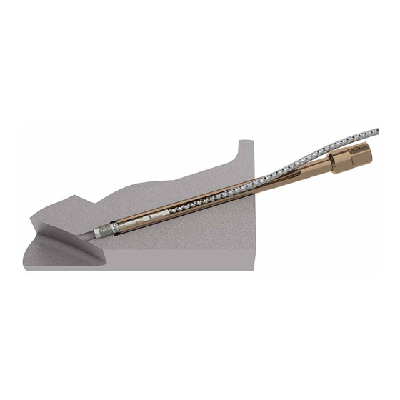
- Page 23 Dismounting and maintenance Fig. 18: Reamer tool Type 1300A79 for reconditioning the front seal of a 5mm sensor bore Procedure: Clean and dry the sensor bore, fill the flutes of the cutter with grease - this collects any swarf building up and re- duces the risk that the cutter sticks. Adjust the preloading force of the finishing tool with the barrel or chuck (using the M5 thread) so that the friction force is small when the cutting head is turned. The finishing operation must feel...
- Page 24 Uncooled piezoelectric pressure sensors Fig. 20: Cleaning the milling surface of the tool - remo- ving swarf build-up Re-inspect the measurement bore to monitor the impro- vement or otherwise to the sealing face. This should be considered an iterative process - a number of attempts should be made to improve the sealing face step-by-step.
-
Page 25: Kistler Technical Center Services
By using the service of Kistler Technical Centers located in Europe, Asia, and America the user benefits safe and reliable operation of the measuring equipment. Thanks to the proximity to the user, the response time is reduced to a minimum;...
Need help?
Do you have a question about the 6056 Series and is the answer not in the manual?
Questions and answers