Table of Contents
Advertisement
Quick Links
Quick Start Installation
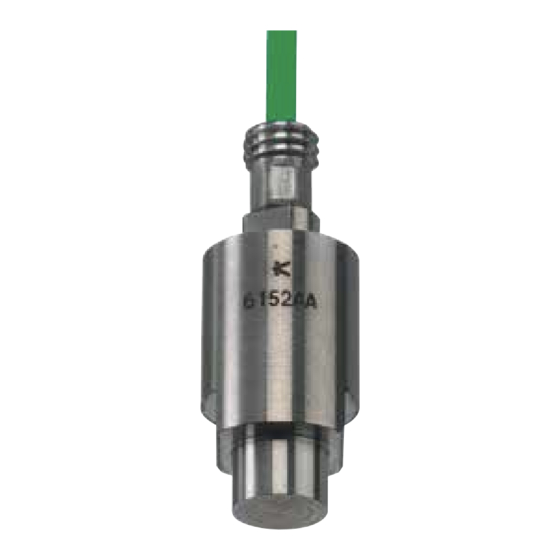
6 mm Cavity Pressure Sensor
Type 6152B... (Unisens
–9,4 pC/bar, 2 000 bar, 200 °C)
®
Type 6162A... (Membrane sensor –18,5 pC/bar, 200 bar, 200 °C)
Type 6163A... (Membrane sensor –3,9 pC/bar, 1 000 bar, 200 °C)
Type 6172B... (HighSens –45 pC/bar, 200 bar, 200 °C)
Content
Front page: machining the mold
1.
General notes
2.
Important areas of sensor bore
3.
Bore
3.1 Unmachined sensor
3.2 Cavity-matched sensor
4.
Cable channeling and connector
4.1 Single-wire cable technology
4.2 Coaxial cable
Rear page: sensor installation, service and repair
5.
Installing sensor
6.
Installing cable and connector
7.
Installing identification plate
8.
Functional test
9.
Service and repair
Foreword
Information in this document is subject to change without
notice. Kistler reserves the right to change or improve its
products and make changes in the content without obliga-
tion to notify any person or organization of such changes or
improvements.
© 2008 ... 2018, Kistler Group. All rights reserved. Kistler
Group products are protected by various intellectual property
rights. For more details visit www.kistler.com.
1. General notes
• Sensor ø6 mm may not be machined
• Front of sensor must be clean and without notches
• Only use recommended installation accessories
• Do not use cable to pull sensor out of bore
2. Important areas of sensor bore
Be aware of the following important areas of the bore:
1. Sensor contact surface must be flat and perpendicular
2. H7 bore to center sensor
3. Chamfer protects O-ring during installation
4. Not to be used to center sensor
5. Sharp edges reduce witness mark on part
3. Bore
3.1 Bore for unmachined sensor
For use in flat cavity wall with sensor fitted at right angles to
cavity
• Bore and thread must be free of debris and shavings
3.1.1 Bore: sensor with mounting nut Type 6453
Electrical discharge machine (EDM), mill or precision grind H7
bore in hardened tool steel. Check centering and alignment.
Clean thread of debris and shavings.
• M12x1 tap may be used for thread
3.1.2 Bore: sensor with spacer sleeve Type 6462
EDM, mill or precision grind H7 bore in hardened tool steel.
Check centering and alignment. Clean thread of debris and
6152B_002-458e-04.18
shavings.
3.2 Bore for cavity-matched sensor
The sensors Types 6152BC..., 6152BD... and 6152BW, as well
as Types 6172BC... and 6172BW... have a chromed front face.
The sensor fronts of these sensors may on no account, be
machined. This is also valid for the sensors Type 6162A... and
6163A..., with welded front.
All liability and warranty claims become void in the case of a
sensor whose front has been machined.
3.2.1 Bore to prevent rotation
The H7-bore can be machined by eroding, drilling or grinding.
For bore dimensions see:
• Chapter 3.1.1 Bore: sensor with mounting nut
• Chapter 3.1.2 Bore: sensor with spacer sleeve
Prevent rotation with bearing surface like it is shown in the
picture.
• Adjust "x" to sensor
• Check radius at base of key
3.2.2 Machining sensor collar
Use sensor collar Ø10 mm with two AF8 plains to position
the sensor.
• No sensor machining necessary.
3.2.3 Machining sensor front
Grind sensor front or install sensor in bore and then machine
complete cavity profile. Then remove sensor with extraction
tool Type 1315A (1362A). Clean bore and sensor.
• only for uncoated Types 6152BA..., 6152BB...,
6152BV..., 6172BA... and 6172BV... permitted
• Use extraction tool Type 1315A (Type 1362A for
Sensor Types 6152BB... and 6152BD...
• Use cleaning spray Type 1003
4. Cable channeling and connector
• Install cables in channels to simplify mold assembly
• Do not route cables next to hot runner cartridge
• Chamfer all sharp edges
• Cover open ducts/slots
4.1 Single-wire cable technology
The single-wire technology uses the tool steel to ensure elec-
trical shielding of the sensor signal. Thus the wiring is routed
through drilled bore.
• Single-wire cable must be completely enclosed in mold
• Single-wire cable may not be routed with power cables
4.1.1 Single-wire cut and grip connector Type 1839
Machine cable channel and recess for mounting plate.
Example shown: bore
Example channel:
4.1.2 Multichannel single-wire connectors
Recess for 4-channel connector Type 1722A4.......
Recess for 8-channel connector Type 1722A8......
4.2 Coaxial cable
Machine cable channel and recess for mounting plate.
6152BA/min. R3
6152BB/min. R5
• Cover open channel to prevent cable damage
Advertisement
Table of Contents

Subscribe to Our Youtube Channel
Related Manuals for Kistler 6152B Series


Summary of Contents for Kistler 6152B Series
- Page 1 Information in this document is subject to change without For bore dimensions see: notice. Kistler reserves the right to change or improve its • Chapter 3.1.1 Bore: sensor with mounting nut products and make changes in the content without obliga- •...
- Page 2 Place cap on open connector. 9.6 Repairs at Kistler Types 6152BB... and 6152BD...) to install sensor • For multi-cavity applications each spacer sleeve Factory repairs at Kistler are arranged by the local sales should be numbered office Information: www.kistler.com 9.7 Disposal instructions for electrical and electronic...
Need help?
Do you have a question about the 6152B Series and is the answer not in the manual?
Questions and answers