Table of Contents
Advertisement
Quick Links
TCI-W13, TCI-W23 Series Wall Mounted Universal Controller
Features
•
Universal PID and/or binary control for any analog
input/output signal and range.
•
Multiple auxiliary functions: heat-cool auto changeover,
automatic enable, setpoint compensation.
•
Differential, averaging, min and max functions
•
Cascading of control loops (-W23 type).
•
Alarm monitoring of low and high limits on all inputs.
•
Programmable reaction in case of alarm.
•
Feedback function for inputs and set points.
•
Functions for dehumidifying, set point shift, cascade
control.
•
Password protected programmable user and control
parameters.
•
Blue backlight.
TCI-W23 also includes
•
Power Cap protected real-time clock with 48hr power
backup.
•
Clock with up to 8 switching events
•
7-day programmable schedules, with options including
change of setpoints and direct position of manual outputs.
Applications
•
Fan coil units
•
Heat exchangers
•
Zoning
General
•
TCI-W13: 1 independent control loop, 1 internal temperature sensor, 1 universal input (analog/binary/temp),
1 binary/PWM output, 2 analog outputs
•
TCI-W23: 2 independent control loops, 8 time schedules, 1 internal temperature sensor, 1 universal input,
1 passive input, 1 binary/PWM output, 2 analog outputs
•
Internal temperature sensor standard. Add replaceable humidity element as required: AES3-HT-A2 (2%), AES3-
HT-A3 (3%), or AES3-HT-A5 (5%)
•
Flexible application configuration is made with a parameter-setting routine using the standard operation terminal.
Product Name
- W
T
C
I
2
Types and Ordering
Product
Product No.
Name
TCI-W13
40-10 0259
TCI-W13-H
40-10 0260
TCI-W23
40-10 0263
TCI-W23-H
40-10 0264
AES3-HT-A2
40-50 0102
AES3-HT-A3
40-50 0103
AES3-HT-A5
40-50 0104
Temperature sensors: Use Vector Controls NTC sensors to achieve maximum accuracy:SDB-Tn10-20 (duct), SRA-Tn10
(room), SDB-Tn10-20 + AMI-S10 as immersion sensor.
Actuators: Choose modulating actuators with an input signal type of 0-10 V DC or 4-20 mA (Min. and max. signal
limitations may be set with parameters.3-pointpoint actuators with constant running time are recommended.
Binary auxiliary devices (e.g. pumps, fans, on/off valves, humidifiers, etc): Do not directly connect devices that exceed
specified limits in technical specifications – observe startup current on inductive loads.
Doc: 70-00-0365C, V2.0, 20220523
Subject to alteration
•
VAV
•
Air handlers
•
Fan, Pump control
-
3
U
Housing
In/Outputs:
Control loops:
Mounting:
Series:
Temperature
Humidity
Loop
Sensor
Sensor
(internal)
(internal)
1
1
2
© Vector Controls GmbH, Switzerland
TCI-W13, TCI-W23 Universal Controller
•
Humidifiers
•
Dehumidifiers
•
Ventilation
Blank = square housing
See table below
1 = 1 control loop, 2 = 2 control loops
W = Wall mounted
TCI
Binary
UI
TI
Output
0
0
1
1
1
0
1
1
1
1
1
•
Radiant heating
•
Radiant cooling
•
Pressurization
Time
Analog
Schedules
Output
0
rH Sensor 3% acc.
2
Time schedules
8
rH Sensor 3% acc.
rH Sensor 2% acc.
rH Sensor 3% acc.
rH Sensor 5% acc.
O
VERVIEW
TCI-W13
TCI-W23
Option
Standard
Page 1-22
Advertisement
Table of Contents

Related Manuals for Vector 40-10 0263


Summarization of Contents
Overview
Features
Key capabilities of the universal controller, including PID control, auto changeover, and alarm monitoring.
Applications
Lists the various systems the controller can manage, such as fan coil units, VAV, and air handlers.
General Controller Information
Provides general specifications for the TCI-W13 and TCI-W23 controllers, including loop count and input/output details.
Technical Specifications
Electrical and Input Specifications
Details power supply requirements, signal input types, ranges, and accuracy for temperature/humidity sensors.
Output and Environmental Specifications
Describes signal outputs, environmental operating conditions, and transport/storage requirements.
Standards and Physical Characteristics
Covers relevant standards, materials, dimensions, weight, and product testing/certification information.
Wiring and Connection
Wiring Diagrams and Terminal Functions
Illustrates electrical connections and explains the function of each terminal on TCI-W13/W23 controllers.
Jumper Settings
Provides guidance on setting jumpers for input and output configurations on the controller.
Mounting and Installation
Mounting Location Recommendations
Recommends ideal locations for controller installation to ensure optimal performance and accessibility.
Installation and Dimension Details
Directs to specific installation sheets and displays physical dimensions for planning.
Display and Operation
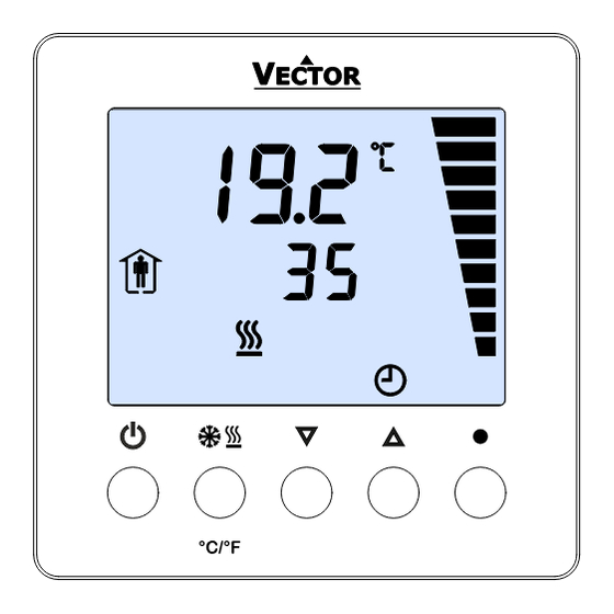
User Interface Element Descriptions
Details the function of each display element, from loop indication to large digits showing measured values.
Operational Modes and Status
Controller Modes and Operational States
Explains controller modes (Occupied, Cooling) and operational states like loop display and OFF mode.
Special Operational Scenarios
Covers special scenarios such as cascade control override, power failure, and alarm messages.
Error Messages and Manual Adjustments
Error Message Interpretation
Lists and explains error codes (Err1, Err3, Err4) and their corresponding conditions for troubleshooting.
Manual Mode Changes and Sensor Calibration
Details manual adjustments for heat/cool mode, input value display, and sensor calibration procedures.
Software Version Identification
Explains how to identify the controller's software version using button combinations.
Clock Operation and Time Schedules
Clock Setup and Management
Guides on setting up the clock, enabling/disabling time schedules, and managing schedule status.
Creating and Applying Time Schedules
Provides step-by-step instructions for creating and applying time schedules for mode changes and setpoints.
Parameter Configuration
Parameter Access and Levels
Defines two access levels for parameters: User/display (0009) and Control (00241).
Recommended Setup Procedure
Outlines the essential steps for setting up and configuring the controller, from jumpers to testing.
Parameter Modules and Modification
Lists parameter modules (UP, 1T/1H/1U/2U, etc.) and explains the process for parameter modification.
User and Display Parameter Details
User/Display Parameter Settings (UP)
Details user and display parameters (UP00-UP18) covering modes, display content, clock, and backlight settings.
Input Configuration
Internal and Universal Input Setup
Configures internal temperature/humidity sensors and universal inputs (1U, 2T) for signal type, range, and alarms.
Input Alarm Configuration
Sets up low/high limit alarms for inputs (ALA1-ALA8) and defines how alarms trigger and are managed.
Input Mathematical Functions
Explains how to calculate mathematical functions (average, min, max, differential) using input values.
Control Loop Configuration
Setpoint Manipulation and Limits
Configures setpoint limits, compensation, and dead zones for heating and cooling control loops.
Cascade Control Setup
Details how to configure cascade control sequences, linking primary and secondary loops for advanced control.
Setpoint Compensation
Explains how to use input values to automatically adjust setpoints for heating or cooling based on conditions.
PI and Integral Control Sequences
PI Control Sequence Parameters
Sets parameters for proportional band (P-band) and offsets for heating and cooling PI sequences.
Integral and Differential Control Setup
Configures integral gain (KI) and measuring intervals for stable temperature control and comfort.
Digital Control Sequences
Stage Actions and Switching Logic
Defines stage actions (cumulative, single, digital) and switching logic for multi-stage control applications.
Switching Hysteresis and Delay
Configures hysteresis and delay settings for digital outputs to manage switching cycles and prevent rapid changes.
Output Configuration
Analog Output Configuration
Configures analog outputs for control loops, special functions, manual positioning, and alarms.
Analog Output Scaling and Alarms
Sets output signal limits, scaling, and assigns alarms to analog output states.
Digital Output Configuration
Digital Output Type and Function Assignment
Selects output type (digital/PWM) and assigns control loop or special function to digital outputs.
Digital Output Alarms and Delays
Configures alarms, switch-off/on delays, and fan symbol display for digital outputs.
PWM Output Configuration
PWM Output Settings and Limits
Details PWM duty cycle limits, activation, and cycle time settings for precise digital output control.
PWM Output Alarms and Important Notes
Assigns alarms to PWM outputs and provides important notes regarding PWM cycle times and relay lifetime.
Auxiliary Functions
Summer/Winter Compensation
Configures temperature-based compensation for heating and cooling setpoints based on outdoor conditions.
Occupied/Unoccupied Mode Switching
Sets up automatic switching between occupied and unoccupied modes using inputs like sensors or key cards.
Enable/Disable Controller Functions
Input-Based Enable/Disable Control
Enables or disables the controller based on input values, with options for delays and limit ranges.
Input Limit Configuration for Control
Defines input limits (Limit 1, Limit 2) used for enabling or disabling controller functions based on input values.
Heating/Cooling Mode Changeover
Input-Driven Mode Switching Logic
Selects an input to drive heating/cooling mode changes, with options for delays and input limits.
Mode Changeover Recommendations
Provides suggested temperature setpoints for switching between heating and cooling based on supply media or outdoor air.
Need help?
Do you have a question about the 40-10 0263 and is the answer not in the manual?
Questions and answers