
Related Manuals for Phcbi MCO-170AICUVD


Summary of Contents for Phcbi MCO-170AICUVD
- Page 1 Operating Instructions Incubator MCO-170AICD MCO-170AICUVD Please read the operating instructions carefully before using this product, and keep the operating instructions for future use. See page 95 for model number. ...
-
Page 3: Table Of Contents
CONTENTS INTRODUCTION ..................3 PRECAUTIONS FOR SAFE OPERATION ........... 4 SYMBOLS ON INCUBATOR ................ 8 ENVIRONMENTAL CONDITIONS ..............8 INCUBATOR COMPONENTS Unit ......................9 LCD touch panel ..................11 Remote alarm terminal ................13 INSTALLATION Installation site ..................14 Installation ....................16 Connecting CO gas cylinder .............. - Page 4 CONTENTS DRY HEAT STERILISATION ..............61 Dry heat sterilisation ................61 ELECTRIC LOCK ..................66 Setting User-ID ..................66 Setting auto lock ..................68 Using unlock key ..................71 Removing auto lock ................. 72 UV LAMP PARAMETERS ................73 Using UV lamp ..................73 Setting UV lamp ON period ..............
-
Page 5: Introduction
INTRODUCTION ■ Read the operating instructions carefully before using the Product and follow the instructions for safety operation. ■ PHC Corporation disavows any responsibility for safety if the Product is used for other than the intended use or used with any procedures other than those given in the operating instructions. ■... -
Page 6: Precautions For Safe Operation
PRECAUTIONS FOR SAFE OPERATION It is imperative that the user complies with the operating instructions as it contains important safety advice. Items and procedures are described so that you can use this unit correctly and safely. If the precautions advised are followed, this will prevent possible injury to the user and any other person. - Page 7 WARNING Do not use the unit outdoors. Current leakage or electric shock may result if the unit is exposed to rain water. Only qualified engineers or service personnel should install the unit. The installation by unqualified personnel may cause electric shock or fire. Install the unit on a sturdy floor and take an adequate precaution to prevent the unit from turning over.
- Page 8 PRECAUTIONS FOR SAFE OPERATION WARNING Ensure you do not inhale or consume medication or aerosols from around the unit at the time of maintenance. These may be harmful to your health. Never splash water directly onto the unit as this may cause electric shock or short circuit. Never put containers with liquid on the unit as this may cause electric shock or short circuit when the liquid is spilled.
- Page 9 WARNING When performing dry heat sterilisation, securely close the internal and external doors. Failure to do so may cause burns. During dry heat sterilisation, plug the access hole with the silicon cap that is provided. Failure to do so may cause burns. Do not use the unlock key to unlock the outer door during dry heat sterilisation even if a power failure occurs.
-
Page 10: Symbols On Incubator
SYMBOLS ON INCUBATOR The symbols are attached to the incubator. The following table describes the symbols. This symbol is attached to covers that access high-voltage electrical components to prevent electric shock. Only a qualified engineer or service personnel should be allowed to open these covers. -
Page 11: Incubator Components Unit
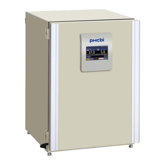
INCUBATOR COMPONENTS Unit Access port Silicon cap Rear side cover Handles Leveling Leveling feet foot Tray 4 (When some inner attachments are removed) Electric key 8 18 Lower right side (When 12 is removed) Removable power * MCO-170AICUVD or when an optional UV Sample air outlet cap supply cord port System Set For Dry Heat MCO-170UVSD is... - Page 12 INCUBATOR COMPONENTS 1. Outer door: The outer door is held to the frame with the magnetic seal. The door heater is installed in the door panel. The door opening is reversible. Contact our sales representative or agent to change the door hinge from left to right or vice versa.
-
Page 13: Lcd Touch Panel
LCD touch panel The following display (called the Top screen) will appear when the power switch is turned ON. Note: It takes approximately 20 seconds until the Top screen is displayed. During warming-up, “Status: Gas sensor initializing” is displayed in the Message display field (13), and “--.-” is displayed in the Present density display field (4). - Page 14 Press this key to lead the Menu screen. It is UV System Set For Dry Heat MCO-170UVSD possible to set various setting on the Menu is not installed to the MCO-170AICD. screen. Refer to page 28. 12. Outer door (opening/closing) display 16.
-
Page 15: Remote Alarm Terminal
17. Unlock key 18. Buzzer key Press this key is to unlock the outer door when Press this key to silence the buzzer. However, it is auto-locked by electric lock. Refer to page when the ring back is ON, the buzzer will 70. -
Page 16: Installation Installation Site
INSTALLATION Installation site For correct operation of the incubator, install it in a location with the following conditions. WARNING When using CO gas for control, make sure that there is an adequate ventilation. Using CO gas in a small room without adequate ventilation may cause gas poisoning or oxygen deprivation. In addition, when opening the incubator doors, do not directly inhale the air in the chamber. - Page 17 Low humidity Select a site with a relative humidity of 80 %R.H. or lower. Using the incubator in high humidity may result in current leakage or electric shock. WARNING Do not use the incubator outdoors. If the incubator is exposed to rain water, it may result in current leakage or electric shock.
-
Page 18: Installation
INSTALLATION Installation 1. Remove the packing tape and clean up. Remove all the tapes that are securing the doors and the inner attachments. Open the doors for ventilation. If the outer panels are dirty, wet a cloth with a diluted neutral detergent and wipe them. (Undiluted detergent can damage the plastic components. - Page 19 5. Ground the incubator. Ground the incubator during installation to prevent electric shock in case the insulation is not sufficient. If there is no ground wire at the location, consult with qualified service personnel. When a ground must be installed If a grounded 3-pole outlet is not available, then a ground must be installed.
- Page 20 INSTALLATION In case of double stack Hooks For stacking the incubators surely, refer to the Wire procedure included with the optional double stacking bracket MCO-170PS or the stacking plate MCO-170SB. Note: ・Two hooks are attached to the rear of the upper incubator.
-
Page 21: Connecting Co Gas Cylinder
Connecting CO gas cylinder WARNING When connecting a gas cylinder to the incubator, confirm the gas type. Confirm that the connections are secure and that no gas will leak. Be sure to use the specified pressure. Using an incorrect gas or pressure may result in explosion or fire, or in gas poisoning or oxygen deprivation due to qas leak. -
Page 22: Before Commencing Operation
BEFORE COMMENCING OPERATION Initial cleaning method Before using the incubator for the first time, clean dirt (tape residue, smear, etc.) from the chamber and the inner attachments thoroughly. To keep the chamber clean is essential to get the proper performance out of the incubator. When the chamber is contaminated or when cleaning the chamber prior to starting a culture, it is possible to perform dry heat sterilisation (refer to pages 61~65). -
Page 23: Removing Inner Attachments
Removing inner attachments CAUTION Wear rubber gloves when performing maintenance on the chamber. Failure to wear gloves may result in cuts or abrasions from sharp edges or corners. Be careful not to damage the UV lamp in the duct (MCO-170AICUVD or when an optional UV System Set For Dry Heat MCO-170UVSD is installed). - Page 24 BEFORE COMMENCING OPERATION 6. Lift the duct and remove it from the pins on the rear side (Fig. 5). Duct Fig. 5 7. Pull out the fan (Fig. 6). Fig. 6 8. Remove the silicon caps of each access port from Silicon cap interior (Fig.
-
Page 25: Installing Inner Attachments
Installing inner attachments To re-install all the attachments, perform the procedure in reverse order from step 8 on page 22. Note: When installing the fan, insert it to the motor 1. Position the center hole of the fan with the shaft securely. -
Page 26: Filling Humidifying Pan
BEFORE COMMENCING OPERATION Filling humidifying pan Use the following procedure to fill the humidifying pan with water or to replace water in the humidifying pan. 1. Pull out the humidifying pan toward you. (Fig. 1) 2. Dispose of the remaining water in the humidifying pan and clean the humidifying pan with a diluted detergent. -
Page 27: For Better Cultivation
FOR BETTER CULTIVATION Precautions for cultures Leave space between culture containers. Always leave space for ventilation between culture containers (Petri dishes, flasks, etc.). Inadequate spacing may result in uneven temperature distribution and CO gas density. Do not place harmful materials in the chamber. Never place samples that release acidic, alkali, or corrosive gas in the chamber. -
Page 28: Preventing Contamination
FOR BETTER CULTIVATION Preventing contamination To prevent contamination of the chamber, select a suitable installation site. Avoid locations with high temperatures or humidity. Avoid locations with high temperatures or humidity, because of a greater presence of microorganisms in the air. ... -
Page 29: Correct Operation
CORRECT OPERATION Use the following procedure to start trial operation or actual operation of the incubator. 1. Install the incubator correctly, referring to “INSTALLATION” on page 14~19. 2. Remove the packing materials from the chamber and inner attachments. Clean and disinfect the chamber and all the inner attachments, referring to “ROUTINE MAINTENANCE”... -
Page 30: Basic Operation On Lcd Touch Panel
BASIC OPERATION ON LCD TOUCH PANEL ●Operation from the Menu key ■Menu screen Page ♦ → ■Stand-by Setting screen (Setting) Temp., CO density, high limit temp. alarm ♦ → ■Log screen ♦ Chart → ■Chart screen ♦ Actual Temp. (Display) Chamber temp. log graph (can be exported) 41 ♦... - Page 31 *1: MCO-170AICUVD or when an optional UV System Set For Dry Heat MCO-170UVSD is installed. *2: When an optional STD gas autocalibration kit MCO-SG is installed. Note: The Service key is not available. (Qualified engineer only) Note: On the Tools #1 screen, by mistakenly pressing the Temp./CO Calibration key, the Calibration screen is displayed.
-
Page 32: Basic Parameters
BASIC PARAMETERS Numerical input to input window On each screen in the LCD touch panel, it may be necessary to input numerical values on the numerical input box. Numerical input box 1. By pressing numerical input box, input window is displayed. -
Page 33: Setting Temperature, Co Density And High Limit Temperature Alarm
Setting temperature, CO density and high limit temperature alarm Set the chamber temperature, the CO density and the temperature of the high limit temperature alarm for normal operation according to the following procedure. The incubator automatically starts operation using these settings after power-on. 1. - Page 34 BASIC PARAMETERS 3. Input each parameter. Press the Apply key to save the input value. The display returns to the Menu screen. ●Each parameter setting · Temperature: Set value of chamber temperature. Settable range: 0.0 C~50.0 C, factory setting: 37.0 ·...
-
Page 35: Setting Key Lock
Setting key lock 1. Press the Menu key to lead the Menu screen. 2. Press the Lock key to lead the Lock screen. 3. Press the KeyLock key to lead the Key Lock screen. - Page 36 BASIC PARAMETERS 4. On the Key Lock screen, it is possible to set each setting of key lock. Press the Apply key to change key lock ON and to save the password. The display returns to the Lock screen. ●Each setting of key lock ·...
-
Page 37: Removing Key Lock
●Operation for Keylock-ON · When pressing any key except the CO supply line select key, the Buzzer key and the Unlock key, Password input box is displayed, and input of the release password of Key Lock is required. · When the inputted password is incorrect, Notice dialog box is displayed. - Page 38 BASIC PARAMETERS 3. Press the Lock key to lead the Lock screen. 4. Press the KeyLock key to lead the Key Lock screen. 5. On the Key Lock screen, by holding the Key Lock slide key and sliding to the left, change to OFF. Press the Apply key to turn the key lock OFF.
-
Page 39: Alarm Parameters
ALARM PARAMETERS 1. Press the Menu key to lead the Menu screen. 2. Press the Tools #1 key to lead the Tools #1 screen. 3. On the Tools #1 screen, ·Press the Alarm Setting #1 key to lead the Alarm Setting #1 screen, it is possible to set automatic set temperature alarm and automatic set CO density... - Page 40 ALARM PARAMETERS 5. On the Alarm Setting #2 screen, it is possible to set each alarm. Press the Apply key to save the input value and setup. The display returns to the Tools #1 screen. ●Each setting · Alarm Delay: The function is that when the incubator is in the alarm state of Automatic set temperature or of Automatic set CO density, the alarm buzzer will sound after the set time of alarm delay passed.
- Page 41 ●At the alarm state · While the incubator’s alarm is activated and the buzzer is sounding, the buzzer is silenced by pressing the Buzzer key. For the behavior at the time of pressing the Buzzer key and the re-activation of alarm, under each setting condition, refer to Table 5~7 on page 87.
-
Page 42: Operation/Alarm/Sterilisation Log Setting Log Interval
OPERATION/ALARM/STERILISATION LOG Setting log interval The incubator is equipped with a function of saving operation log data (chamber temperature, CO density and open/close state of outer door). Use the following procedure to set the log interval (interval of acquiring the operation log). 1. -
Page 43: Displaying Operation Log
4. On the Setting screen, input Log Interval. Press the Apply key to save the input value. The display returns to the Log screen. Settable range: 2 minutes~30 minutes. Factory setting: 6 minutes. Note: It is possible to register 8-digit alphanumeric characters as the Unique ID. - Page 44 OPERATION/ALARM/STERILISATION LOG 3. Press the Chart key to lead the Chart screen. 4. On the Chart screen, input the date (year / month / day) of the operation log you want to display graphically. 5. On the Chart screen, by pressing the Show key after pressing the item you want to display graphically, the graph of each operation log is displayed.
- Page 45 6. Actual Temp. log graph is displayed. To previous day To next day · Press the Back key to return to the Chart screen. · Press the Top key to return to the Top screen. To Actual CO Level log To Actual Temp.
- Page 46 OPERATION/ALARM/STERILISATION LOG ●On each log graph screen of procedure 6, 7 or 8, operation log data can be exported in CSV format to the USB memory inserted into the USB port. 9. Insert the USB memory into the USB port. Note: It is not possible to use a USB memory with security functions that requires entering password.
-
Page 47: Exporting Operation Log
Exporting operation log Operation log data saved in the incubator can be exported in CSV format to the USB memory inserted into the USB port. 1. Insert the USB memory into the USB port. Note: It is not possible to use a USB memory with security functions that requires entering password. 2. - Page 48 OPERATION/ALARM/STERILISATION LOG 5. On the Export screen, select the time period you want to export. · To export the saved operation log data over the entire period, press the All radio button. · To export the operation log data of a specified date, press the 1 Day radio button and input the date (year / month / day) of the operation log data you want to export.
- Page 49 * In the case of AllCh, Door Opening log file is also export together. · On the beginning of the exported file, “MCO-170AICD” is written. However when the Unique ID is registered (refer to page 41), “MCO-170AICD” and Unique ID (8-digit) are written.
-
Page 50: Displaying Alarm Log
OPERATION/ALARM/STERILISATION LOG Displaying alarm log The incubator is equipped with a function of saving alarm log data (Max. 256 logs). Alarm log saved in the incubator can be displayed graphically on the LCD touch panel. Note: When saving alarm logs more than 257, the oldest alarm log is deleted, and then overwritten. 1. - Page 51 4. On the Alarm screen, alarm logs in the latest 7 days containing that day are displayed. Note: If there are 6 or more alarm logs in the latest 7 days, by pressing the top (▲) or the bottom (▼) log, the log table scrolls one by one and hidden alarm logs can be seen.
-
Page 52: Exporting Alarm Log
OPERATION/ALARM/STERILISATION LOG Exporting alarm log It is possible to export saved alarm log data to a USB memory inserted in the USB port by CSV format. 1. Insert a USB memory in the USB port. Note: It is not possible to use a USB memory with security functions that requires entering password. 2. - Page 53 5. On the Alarm Export screen, select the period to export. · To export the saved alarm log data over the entire period, press the All radio button. · To export the alarm log data in the specified days (The latest period containing that day), press the Last XX Days radio button and input days.
- Page 54 OPERATION/ALARM/STERILISATION LOG 7. Even after completion the export of alarm log data, Information dialog box is displayed. Press the OK key. Note: After completing the export of alarm log data, alarm log data saved at the incubator is not deleted. 8.
-
Page 55: Displaying Sterilisation Log
Displaying sterilisation log The incubator is equipped with a function of saving dry heat sterilisation log data (Max. 250 logs). Sterilisation logs saved in the incubator can be displayed graphically on the LCD touch panel. Note: When saving sterilisation logs more than 251, the oldest alarm log is deleted, and then overwritten. 1. - Page 56 OPERATION/ALARM/STERILISATION LOG 4. On the Sterilisation Log screen, the latest 6 sterilisation logs are displayed. Note: When 7 or more sterilisation logs exist, by pressing the top (▲) or the bottom (▼) log, the log table scrolls one by one and hidden sterilisation logs can be seen.
-
Page 57: Exporting Sterilisation Log
Exporting sterilisation log It is possible to export saved sterilisation log data to a USB memory inserted in the USB port by CSV format. 1. Insert a USB memory in the USB port. Note: It is not possible to use a USB memory with security functions that requires entering password. 2. - Page 58 OPERATION/ALARM/STERILISATION LOG 5. On the Sterilisation Export screen, select the period to export. · To export the saved sterilisation log data over the entire period, press the All radio button. · To export the latest sterilisation log data of the specified number of logs, press the Last XX Logs radio button and input the number of logs.
- Page 59 7. Even after completion the export of sterilisation log data, Information dialog box is displayed. Press the OK key. Note: After completing the export of sterilisation log data, sterilisation log data saved at the incubator is not deleted. 8. Remove the USB memory from the USB port. Note: A log folder is created in the USB memory, and the exported data file is saved in it by CSV format.
-
Page 60: Other Parameters
OTHER PARAMETERS Setting date and time 1. Press the Menu key to lead the Menu screen. 2. Press the Tools #2 key to lead the Tools #2 screen. 3. Press the Date & Time key to lead the Date & Time screen. -
Page 61: Setting Brightness And Sleep
5. On the Date & Time screen, input the present date and time. Press the Apply key to save the input value. The display returns to the Tools #2 screen. Note: · 24-hour clock. · It is recommended to set the time periodically since the error of about 1 minute may be observed during a month. - Page 62 OTHER PARAMETERS 4. On the Brightness/Sleep screen, each setting of brightness and sleep is available. Press the Apply key to save the input value and setup. The display returns to the Tools #2 screen. ●Each setting · Brightness(Active): Brightness of LCD touch panel of the usual state. Adjust the Brightness(Active) slide bar or input set value into the Brightness(Active) input box.
-
Page 63: Dry Heat Sterilisation
DRY HEAT STERILISATION When the chamber is contaminated or when cleaning the chamber prior to starting a culture, it is possible to perform dry heat sterilisation. Note: · Dry heat sterilisation temperature and time: 180 C - 60 minutes. · Dry heat sterilisation is allowed under following ambient conditions: Temperature: 15 C~30 C, humidity: 80 %R.H. - Page 64 DRY HEAT STERILISATION 5. Clean the humidifying pan with a diluted detergent. Then rinse it thoroughly with distilled water and wipe it with a gauze containing alcohol for disinfection. 6. Wipe the other inner attachments removed from the chamber and inside walls with a gauze containing alcohol for disinfection.
- Page 65 12. On the Sterilisation Step1 screen, the system check starts automatically. If the system is normal, the display leads the Sterilisation Step2 screen. Note: If the system is abnormal, the display leads the Sterilisation Step6 screen. Resolve the cause of the error displayed in the message display field, in reference to Table 8 on page 88~89.
- Page 66 DRY HEAT STERILISATION ●Step3 is the process to heat the inside of the chamber to 180 C (heating process). · After the entire inside of the chamber exceeds C, the display leads the Sterilisation Step4 screen. The displayed temperature comes to more than 180 C sometimes.
- Page 67 14. After dry heat sterilisation is completed, buzzer sounds and the Sterilisation Step6 screen is displayed. heat sterilisation finishes successfully, “Sterilisation Finished Successfully.” is displayed. Press the OK key to return to the Top screen. Note: If dry heat sterilisation ends in failure by something abnormal during dry heat sterilisation, “Sterilisation Stopped With Error.”...
-
Page 68: Electric Lock
ELECTRIC LOCK Auto lock function is that the outer door is locked automatically when the setting time passed after the door closed. The modes of unlocking the outer door are as follows. · Quick mode: Press the Unlock key. · User-ID mode: Input the User-ID and release password of Auto-Lock, after pressing the Unlock key. Setting User-ID Before turning the User-ID mode to ON, use the following procedure to register a User-ID and a release password of Auto-Lock. - Page 69 4. On the Auto-Lock User screen, it is possible to register a User-ID and its password. Press the Apply key to save the User-ID and its password. ●Each setting of Auto-Lock · User-ID: The alphanumeric characters (Max. 8-digit) inputted here are registered as a new User-ID. ·...
-
Page 70: Setting Auto Lock
ELECTRIC LOCK ●Changing a registered User-ID’s password Input the registered User-ID into User-ID input box, and input its new password into Password input box and Confirm Password box. Press the Add key to re-write the new password. ●Deleting a registered User-ID Input the registered User-ID into User-ID input box, and input its registered password into Password input box. - Page 71 4. On the Auto-Lock screen, each setting of auto lock is available. Press the Apply key to turn the auto lock ON and save the set value. The display returns to the Lock screen. ●Each setting of auto lock · Auto-Lock: Auto lock function is that the outer door is locked automatically when the setting time passed after the door closed.
- Page 72 ELECTRIC LOCK ●Unlocking the outer door · In the quick mode, press the Unlock key on the Top screen to unlock the outer door. · In the User-ID mode, when pressing the Unlock key on the Top screen, User-ID input box is displayed.
-
Page 73: Using Unlock Key
Using unlock key Unlocking when a power failure occurrs The outer door is locked with electric lock under a power failure. To unlock the outer door while a power failure occurs, use the unlock key that is provided. To re-lock the outer door, turn the unlock key to the lock direction while the outer door is open. -
Page 74: Removing Auto Lock
ELECTRIC LOCK Removing auto lock 1. Press the Menu key to lead the Menu screen. 2. Press the Lock key to lead the Lock screen. 3. Press the Auto-Lock key to lead the Auto-Lock screen. 4. On the Auto-Lock screen, by holding the Auto-lock slide key and sliding it left, the Auto-lock is turned to OFF. -
Page 75: Uv Lamp Parameters
MCO-170AICUVD or when an optional UV System Set For Dry Heat MCO-170UVSD is installed to the MCO-170AICD, UV lamp is workable. After closing the outer door, UV lamp lights for the preset period*, to disinfect the water in the humidifying pan, and to disinfect the air circulating in the chamber. -
Page 76: Setting Uv Lamp On Period
UV LAMP PARAMETERS The recommended replacement time for the UV lamp (i.e., when the UV output ratio drops to 60 % to 70 % of its initial value) is when the accumulated ON time reaches 5,000 hours. When the accumulated ON time reaches approximately 5,000 hours, “Warning: UV Bulb Life”... - Page 77 4. On the UV Setting screen, each setting of UV is available. Press the Apply key to save the input value and setup. The display returns to the Tools #1 screen. ●Each setting · UV Timer: Set value of period to light UV lamp after closing the outer door. Settable range: 0 minute~30 minutes, factory setting: 10 minutes.
-
Page 78: Lighting Uv Lamp For 24 Hours
UV LAMP PARAMETERS Lighting UV lamp for 24 hours If the chamber has been contaminated by dirt or by spilling the medium, use the following procedure to disinfect the chamber by lighting the UV lamp for 24 hours. 1. Remove attachments from the chamber, including the trays, the fan cover, the duct, the fan, the humidifying pan, and the humidifying pan cover. - Page 79 7. On the UV Setting screen, by holding the UV 24h Mode slide key and sliding it right, the UV 24h Mode is turned to ON. Press the Apply key to start the UV 24-hour mode. The display returns to the Tools #1 screen.
-
Page 80: Gas Auto Changer (Option)
GAS AUTO CHANGER (OPTION) When an optional gas auto changer MCO-21GC is installed, there are two connecting ports for CO pipe, A and B. By connecting two CO gas cylinders, this kit switches the CO gas supply line when one of the CO gas cylinders becomes empty. -
Page 81: Automatic Co 2 Gas Supply Line Changeover
Automatic CO gas supply line changeover When an optional gas auto changer MCO-21GC is installed, CO gas supply line indicator A•B and the gas supply line select key are displayed in the Top screen. The CO gas supply line indicator A or B used now lights. - Page 82 GAS AUTO CHANGER (OPTION) When the CO density level remains unchanged, even though the CO gas valve in the unit is opened, the unit regards the present connecting CO gas cylinder as an empty. The CO gas supply line is changed over automatically.
-
Page 83: Manual Co Gas Supply Line A/B Changeover
Manual CO gas supply line A/B changeover It is possible to change CO gas supply line A/B manually anytime. Example) Change CO gas supply line A to B. 1. Press the CO gas supply line select key for a few seconds. 2. -
Page 84: Std Gas Auto Calibration Kit (Option)
STD GAS AUTO CALIBRATION KIT (OPTION) When a STD gas auto calibration kit MCO-SG is installed, by connecting standard gas cylinder for calibration, it is possible to calibrate CO density manually. 1. Connect a standard gas cylinder to connecting Lower right side port for standard gas cylinder on lower right side of the CO incubator. - Page 85 5. On the STD Gas Setting screen, input CO density of the connected standard CO gas cylinder. Press the Apply key to save the input value. The display returns to the Tools #1 screen. Settable range: 4.0 %~21.0 %. Factory setting: 5.0 %. 6.
- Page 86 STD GAS AUTO CALIBRATION KIT (OPTION) 9. On the STD Gas Calibration Step3 screen, CO density calibration starts. Calibration go to Step5 (Procedure 10) automatically. 10. After completion of CO density calibration, display leads the STD Gas Calibration Step5 screen. CO incubator returns to the normal operation.
-
Page 87: Routine Maintenance
ROUTINE MAINTENANCE To use this unit in a clean condition, clean the chamber and all the inner attachments at least once a month. 1. Remove all the inner attachments by the procedures shown on page 21. 2. Clean the chamber and all the inner attachments by the procedures shown on page 20. 3. -
Page 88: Alarms, Safety, And Self-Diagnosis
ALARMS, SAFETY, AND SELF-DIAGNOSIS The incubator supports the following alarms, safety functions, and self-diagnostic functions. If an error from Err05 to Err18, Err21 or Err56 is activated, contact our sales representative or agent. Table 4 Alarms, safety, and self-diagnosis for culture operations Alarm or safety Remote Safety... - Page 89 Alarm or safety Remote Safety Conditions Display Buzzer function alarm operation a) High limit temperature alarm is activated. Heater SSR “Err17: Heater SSR Open” is displayed in Intermittent ----- b) Main, bottom, door, or sensor box burnout* tone the message display field. heater SSR burnout occurs.
- Page 90 ALARMS, SAFETY, AND SELF-DIAGNOSIS Table 8 Alarms and Safety functions for dry heat sterilisation Sterilisation Message display Remote Sterilisation Conditions Action Buzzer procedure field alarm During a power failure Recovery from power failure Before The power switch is OFF. ----- ----- ↓...
- Page 91 Sterilisation Message display Remote Sterilisation Conditions Action Buzzer procedure field alarm During a power failure (After recovery The power switch is OFF. from power failure) Intermittent Err51: tone The removable power supply Continue Sterilisation step5 Power Failure ↓ cord is disconnected. During Sterilisation step6 cooling...
-
Page 92: Troubleshooting
TROUBLESHOOTING If the incubator does not seem to be working properly, check the following items before calling for service. Symptom Items to check and countermeasures Is the incubator plugged in? The incubator does not operate at all. Is there a power failure, or has a circuit breaker interrupted the power? ... - Page 93 Symptom Items to check and countermeasures Is the ambient air environment around the incubator normal? Is there a source of polluted Normal cultures are not possible, and the CO gas density is gas in the vicinity? suspect. The CO gas is not being injected.
-
Page 94: Disposal Of Unit
DISPOSAL OF UNIT When disposing of the CO incubator, contact our sales representative or agent. WARNING The CO incubator must be dismantled and disposed of by qualified personnel only. If the CO incubator is left where outsiders enter, it may result unexpected accident (for example, children to become locked inside). -
Page 95: Specifications
SPECIFICATIONS Incubator Incubator Product name MCO-170AICD MCO-170AICUVD External dimensions W620 mm x D755 mm x H905 mm Internal dimensions W490 mm x D523 mm x H665 mm 165 L Interior volume Painted steel (Rear cover has no paint) Exterior Interior... - Page 96 *Only for the Data acquisition system MTR-5000 user. Note: Refer to the updated catalog when ordering an optional component. Designs and specifications are subject to change without notice. Table 10 Required bracket/plate for each incubator combination of double stacking MCO-170AICD series Upper product MCO-170AIC series MCO-170M series...
-
Page 97: Performance
PERFORMANCE Incubator MCO-170AICD Product name MCO-170AICUVD MCO-170AICD-PK Model number MCO-170AICUVD-PK AC 220 V, 60 Hz Rated voltage, frequency During cultivation Ambient temperature+5 C to 50 C* (ambient temperature: 5 C to 35 Temperature control range ±0.25 C (ambient temperature: 23... -
Page 98: Safety Check Sheet
CAUTION Please fill in this form before servicing. Hand over this form to the service engineer to keep for his and your safety. Safety check sheet 1. Unit contents : □ □ Risk of infection: □ □ Risk of toxicity: □... - Page 100 1-1-1 Sakada, Oizumi-machi, Ora-gun, Gunma 370-0596, Japan Printed in Japan LDCL040200-0 © PHC Corporation 2018 S0418-0...
Need help?
Do you have a question about the MCO-170AICUVD and is the answer not in the manual?
Questions and answers