
Related Manuals for Phcbi MDF-U5412H


Summary of Contents for Phcbi MDF-U5412H
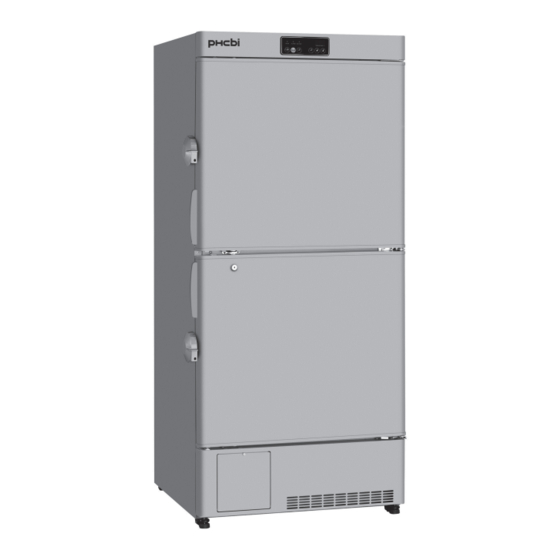
- Page 1 Operating Instructions Biomedical Freezer MDF-U5412H Please read the operating instructions carefully before using this product, and keep the operating instructions for future use. See page 42 for model number.
-
Page 2: Table Of Contents
CONTENTS INTRODUCTION P. 3 PRECAUTIONS FOR SAFE OPERATION P. 4 LABELS ON THE UNIT P. 9 SYMBOLS ON THE UNIT P. 10 ENVIRONMENTAL CONDITIONS P. 11 INTENDED USE AND PRECAUTIONS P. 11 FREEZER COMPONENTS Main body P. 12 Control panel P. -
Page 3: Introduction
INTRODUCTION ■ Read the operating instructions carefully before using the product and follow the instructions for safe operation. ■ PHC Corporation takes no responsibility for safety if the product is not used as intended or is used with any procedures other than those given in the operating instructions. ■... -
Page 4: Precautions For Safe Operation
PRECAUTIONS FOR SAFE OPERATION It is imperative that the user complies with the operating instructions as it contains important safety advice. Items and procedures are described so that you can use this unit correctly and safely. If the precautions advised are followed, this will prevent possible injury to the user and any other person. - Page 5 PRECAUTIONS FOR SAFE OPERATION WARNING Do not use the unit outdoors. Current leakage or electric shock may result if the unit is exposed to rain water. Only qualified engineers or service personnel should install the unit. The installation by unqualified personnel may cause electric shock or fire. Install the unit on a sturdy floor and take an adequate precaution to prevent the unit from turning over.
- Page 6 PRECAUTIONS FOR SAFE OPERATION WARNING Do not touch any electrical parts (such as power supply plug) or operate switches with a wet hand. This may cause electric shock. Ensure you do not inhale or consume medication or aerosols from around the unit at the time of maintenance.
- Page 7 PRECAUTIONS FOR SAFE OPERATION WARNING The replacement of the battery for power failure alarm should be executed by a qualified engineer or a service personnel only. The replacement of the battery for power failure alarm involves the risk of electric shock. Install the unit in a well-ventilated (airy) location to prevent the accumulation of flammable refrigerant.
- Page 8 PRECAUTIONS FOR SAFE OPERATION CAUTION This unit must be plugged into a dedicated circuit protected by branch circuit breaker. Use a dedicated power source as indicated on the rating label attached to the unit. multiple-tap may cause fire resulting from abnormal heating. Connect the power supply plug to the power source firmly after removing the dust on the plug.
-
Page 9: Labels On The Unit
LABELS ON THE UNIT <Warning safety labels applied to the unit> Users are advised to avoid accidents by carefully reading the warnings and cautions contained on warning labels at key locations on the interior and exterior of the unit. Possible Warning/Caution Type Warning/Caution Label Description of Danger... -
Page 10: Symbols On The Unit
SYMBOLS ON THE UNIT The symbols are attached to the unit. The following table describes the symbols. This symbol is attached to covers that access high-voltage electrical components to prevent electric shock. Only a qualified engineer or service personnel should be allowed to open these covers. -
Page 11: Environmental Conditions
ENVIRONMENTAL CONDITIONS This equipment is designed to be safe at least under the following conditions (based on the IEC61010-1): ■ Indoor use; ■ Altitude up to 2000 m; ■ Ambient temperature 5 C to 40 ■ Maximum relative humidity 80% for temperature up to 31 C decreasing linearly to 50% relative humidity at 40 ■... -
Page 12: Freezer Components
FREEZER COMPONENTS Main body 10 11... - Page 13 FREEZER COMPONENTS 1. Control panel: The chamber temperature and alarms can be set through the keys on the control panel. The temperature display and indicators are also provided on the control panel [page 14]. 2. Lock: By using with the enclosed key, both the upper door and lower door are locked or unlocked. 3.
-
Page 14: Control Panel
FREEZER COMPONENTS Control panel 1. Door check indicator (DOOR): 6. Scroll key ( The red LED lamp is lit when the door is open. At “temperature display mode”; Depressing this The buzzer sounds 2 minutes (initial setting) key for more than 5 seconds leads the setting of after lighting of door check indicator to inform the “lock of chamber temperature setting”... - Page 15 FREEZER COMPONENTS 8. Defrost key (DEF.): 10. Alarm test key (ALARM TEST): At “temperature display mode”; depressing this This key is used to check the operation of key for more than 5 seconds leads the stop of buzzer, alarm indicator and remote alarm freezer operation.
-
Page 16: Installation Site
INSTALLATION SITE To operate this unit properly and to obtain maximum performance, install the unit in a location with the following conditions: A location not subjected to direct sunlight Do not install the unit under direct sunlight. Installation in a location subjected to direct sunlight cannot obtain the intended performance. -
Page 17: Installation
INSTALLATION When installing the unit, follow the steps below to secure the unit properly, and also be absolutely sure to connect the unit to ground. In addition, install a ground fault circuit breaker (on the unit’s power supply side) which is mandatory under the applicable laws and regulations. - Page 18 INSTALLATION 4. Preventing electric shock by connecting the unit to ground When installing the unit, be absolutely sure to connect it to ground. Grounding is necessary to prevent the electric shock which will arise when the electrical insulation has deteriorated. WARNING Use a power supply outlet with ground (earth) to prevent electric shock.
-
Page 19: Start-Up Procedure
START-UP PROCEDURE To commence the operation (initially or after temporary power off due to the cleaning, maintenance, etc.), follow the procedure below: The operation is resumed automatically at the recovery from power failure with the setting before power failure [page 27]. 1. -
Page 20: Setting Of Chamber Temperature
SETTING OF CHAMBER TEMPERATURE Set the chamber temperature as needed to keep the material at appropriate temperature for long period of time. Setting range of chamber temperature: between -45 C and-18 Initial setting (factory setting): -40 <Important> The setting range of chamber temperature is between -45 C and -18 C, however the guaranteed chamber temperature with no load is -40... -
Page 21: Lock Of Chamber Temperature Setting
LOCK OF CHAMBER TEMPERATURE SETTING The chamber temperature setting can be locked to avoid an accidental change. The change of chamber temperature setting is not accepted even if the key on the control panel is operated when the lock is ON. ... -
Page 22: Setting Of Alarm Temperature
SETTING OF ALARM TEMPERATURE Setting of high temperature alarm The abnormality (chamber temperature rise) is noticed by blinking of alarm indicator and chamber temperature display and sounding of the buzzer (15 minutes after blinking) if the chamber temperature exceeds the set value of high temperature alarm. Always set the high temperature alarm to protect the storage items from damage resulting from temperature rise. -
Page 23: Setting Of Low Temperature Alarm
SETTING OF ALARM TEMPERATURE Setting of low temperature alarm The abnormality (chamber temperature drop) is noticed by blinking of alarm indicator and chamber temperature display and sounding of the buzzer (15 minutes after blinking) if the chamber temperature exceeds the set value of low temperature alarm. Always set the low temperature alarm to protect the storage items from damage resulting from temperature drop. -
Page 24: Setting Of Door Alarm Delay
SETTING OF DOOR ALARM DELAY The door check indicator is lit when the door is opened, and the buzzer sounds with some delay to notice the door opening. The delay time (between lighting of the door check indicator and activation of the buzzer) can be changed. Set an appropriate delay time according to the condition of use to prevent the rise of chamber temperature resulting from inadequate door close. -
Page 25: Setting Of Buzzer Suspended Period
SETTING OF BUZZER SUSPENDED PERIOD The abnormality is noticed again by sounding of the buzzer after certain suspended period (buzzer recovery timing) if the alarm status continues even after the buzzer is silenced by depressing the buzzer stop key (BUZZER). Always set the buzzer suspended period to avoid the wrong recognition of alarm status ... -
Page 26: Setting Of Compressor Start Delay
SETTING OF COMPRESSOR START DELAY The delay time of compressor start can be changed to reduce the load on the power line and to facilitate the start-up (reset) of the freezer at the recovery after power failure. Setting range of delay time: between 3 and 15 minutes with 1 minute interval ... -
Page 27: During/After Power Failure
DURING/AFTER POWER FAILURE Display of chamber temperature during power failure By depressing the buzzer stop key (BUZZER) during “power failure alarm”, the buzzer stops and the chamber temperature is displayed on the temperature display for 5 seconds. Check the chamber temperature as appropriate by depressing the buzzer stop key (BUZZER) during power failure. -
Page 28: Remote Alarm Terminal
REMOTE ALARM TERMINAL The alarm status is noticed to a remote location when a remote alarm equipment (commercial item) is connected to the remote alarm terminal. It is recommended to install a remote alarm equipment (commercial item) when the freezer is installed in a desolate location so that an alarm status is noticed to an operator. -
Page 29: Alarm Functions
ALARM FUNCTIONS This unit has the alarm functions shown below. When an alarm has been generated, check the cause on the basis of the type of alarm generated, and take the necessary action to deal with it without delay. Contact our sales representative or agent if the alarm is not released by eliminating the following cause. Before calling for service, take some precautions for the storage items (placing of dry ice wrapped in newspaper in the chamber or transferring the storage items to another freezer). -
Page 30: Self Diagnostic Functions
SELF DIAGNOSTIC FUNCTIONS Alarms involving an error code indicated on the temperature display are generated by the self diagnostic function. Contact our sales representative or agent without delay, report the error code and request repairs. Self diagnostic Cause Indication Buzzer Remote alarm The alarm indicator blinks. -
Page 31: Routine Maintenance
ROUTINE MAINTENANCE WARNING Turn off the power switch and disconnect the power supply to the unit prior to any maintenance. Failure to follow this may cause electric shock or injury. WARNING Ensure you do not inhale or consume medication or aerosols from around the unit at the time of maintenance. -
Page 32: Defrosting
ROUTINE MAINTENANCE Defrosting The freezer has no automatic defrosting system. Stop the freezer operation and remove the frost when the frost is accumulated in the freezer. WARNING Never damage the chamber wall or pipework in the chamber when removing the frost. flammable refrigerant may cause fire if it leaks. -
Page 33: Replacement Of Battery
REPLACEMENT OF BATTERY Replace the battery for power failure alarm every 3 years (when the battery indicator is lit) to ensure the alarm is operated in the event of power failure. Contact our sales representative or agent for the replacement of battery when the battery indicator is lit. The alarm function (blink of alarm indicator, sound of buzzer) will not operate when the battery for power failure alarm is flat. -
Page 34: Troubleshooting
TROUBLESHOOTING If the unit malfunctions, check out the following before calling for service. Malfunction Check/Remedy If nothing operates even □ The unit is not connected to the power supply properly. when plugged in □ The capacity and voltage of power supply is not sufficient. □... -
Page 35: Disposal Of Unit
DISPOSAL OF UNIT WARNING The disposal of the unit should be accomplished by appropriate personnel. Leaving the unit in an unsupervised area may cause accidents. WARNING Flammable and explosive product. The unit contains flammable refrigerant. Be sure to follow the below instructions when servicing or recycling. - Page 36 DISPOSAL OF UNIT (English) Disposal of Old Equipment and Batteries Only for European Union and countries with recycling systems These symbols on the products, packaging, and/or accompanying documents mean that used electrical and electronic products and batteries must not be mixed with general household waste. For proper treatment, recovery and recycling of old products and used batteries, please take them to applicable collection points in accordance with your national legislation.
- Page 37 DISPOSAL OF UNIT (French) L’élimination des équipements et des batteries usagés Applicable uniquement dans les pays membres de l’Union européenne et les pays disposant de systèmes de recyclage. Apposé sur le produit lui-même, sur son emballage, ou figurant dans la documentation qui l’accompagne, ce pictogramme indique que les piles, appareils électriques et électroniques usagés, doivent être séparées des ordures ménagères.
- Page 38 DISPOSAL OF UNIT (Portuguese) Eliminação de Equipamentos Usados e Baterias Apenas para a União Europeia e países com sistemas de reciclagem Estes símbolos nos produtos, embalagens, e/ou documentos que os acompanham indicam que os produtos elétricos e eletrónicos e as baterias usados não podem ser misturados com os resíduos urbanos indiferenciados.
- Page 39 DISPOSAL OF UNIT (Dutch) Het ontdoen van oude apparatuur en batterijen. Enkel voor de Europese Unie en landen met recycle systemen. Deze symbolen op de producten, verpakkingen en/of begeleidende documenten betekenen dat gebruikte elektrische en elektronische producten en batterijen niet samen mogen worden weggegooid met de rest van het huishoudelijk afval.
-
Page 40: Temperature Recorder (Option)
TEMPERATURE RECORDER (OPTION) The chamber temperature can be monitored and recorded by installing an optional temperature recorder. For the installation of a temperature recorder, an optional recorder fixing is necessary. For the attachment of a temperature recorder, contact our sales representative or agent. ... -
Page 41: Specifications
SPECIFICATIONS Product name Biomedical freezer MDF-U5412H Medical purpose Storage of DNAs, plasma External dimensions W804 mm x D772 mm x H1802 mm Internal dimensions W658 mm x D607 mm x H1272 mm Effective capacity 482 L Exterior Painted steel Interior... -
Page 42: Performance
PERFORMANCE Biomedical freezer Product name MDF-U5412H Model number MDF-U5412H-PE Cooling performance C (ambient temp.;30 C, no load) Temperature control range C to -20 C (ambient temp.;5 C to 30 C, no load) Rated voltage 230 V/240 V Rated frequency 50 Hz... -
Page 43: Safety Check Sheet
CAUTION Please fill in this form before servicing. Hand over this form to the service engineer to keep for his and your safety. Safety check sheet 1. Freezer contents : □ □ Risk of infection: □ □ Risk of toxicity: □... - Page 44 Original Operating Instructions < EU countries only > 0123 Nijverheidsweg 120 4879 AZ Etten Leur, The Netherlands Printed in Japan 1-1-1 Sakada, Oizumi-machi, Ora-gun, Gunma 370-0596, Japan LDCL035200-0 S0418-0 2018.04.01 © PHC Corporation 2018...
Need help?
Do you have a question about the MDF-U5412H and is the answer not in the manual?
Questions and answers