
Subscribe to Our Youtube Channel
Related Manuals for Phcbi MBR-305GR


Summary of Contents for Phcbi MBR-305GR
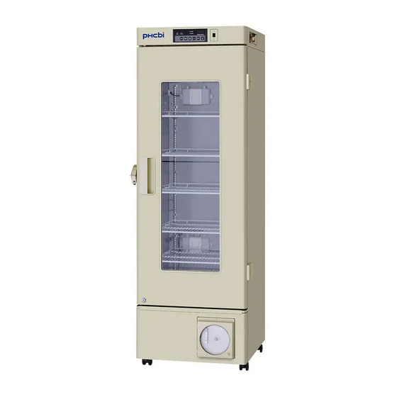
- Page 1 Operating Instructions Blood Bank Refrigerator MBR-305GR Please read the operating instructions carefully before using this product, and keep the operating instructions for future use. See page 34 for model number.
-
Page 2: Table Of Contents
CONTENTS INTRODUCTION ································································· 3 PRECAUTIONS FOR SAFE OPERATION ································· 4 LABELS ON UNIT ································································ 9 SYMBOLS ON UNIT ····························································· 9 ENVIRONMENTAL CONDITIONS ··········································· 9 REFRIGERATOR COMPONENTS Refrigerator unit ······························································ 10 Control panel ·································································· 12 INSTALLATION SITE ··························································· 13 INSTALLATION ··································································· 14 PREPARATION OF MONITOR BOTTLE···································... -
Page 3: Introduction
INTRODUCTION Read the operating instructions carefully before using the product and follow the instructions for safe operation. PHC Corporation takes no responsibility for safety if the product is not used as intended or is used with any procedures other than those given in the operating instructions. ... -
Page 4: Precautions For Safe Operation
PRECAUTIONS FOR SAFE OPERATION It is imperative that the user complies with the operating instructions as they contain important safety advice. Items and procedures are described so that you can use this unit correctly and safely. Following these precautions will prevent possible injury to the user and any other person. - Page 5 PRECAUTIONS FOR SAFE OPERATION WARNING Do not use the unit outdoors. Exposure to rain may cause leakage and/or electric shock. Only qualified engineers or service personnel should install the unit. Installation by unqualified personnel may cause water leakage, electric shock, or fire. Install the unit in a location capable of bearing the total combined weight (product + optional accessories + stored items).
- Page 6 PRECAUTIONS FOR SAFE OPERATION WARNING When handling harmful samples (for example, those which consist of toxic, pathogenic, or radioactive substances), install the unit inside a designated isolation facility. If the unit is installed in a location which is not an isolation facility, there may be detrimental effects on both people and the natural environment.
- Page 7 PRECAUTIONS FOR SAFE OPERATION WARNING Disconnect the power supply plug before moving unit. Take care not to damage the power supply cord. A damaged power supply cord may cause electric shock or fire. Disconnect the power supply cord when the unit is not in use for long periods. Keeping the unit connected may cause electric shock, leakage, or fire due to the deterioration of insulation.
- Page 8 PRECAUTIONS FOR SAFE OPERATION CAUTION Never install the unit in a location where corrosive materials such as sulphur compounds are likely to be generated (e.g. near a drainage facility). Corrosion of the copper pipes may result in the deterioration and consequently the failure of the cooling unit. This unit must be plugged into a dedicated circuit protected by branch circuit breaker.
-
Page 9: Labels On Unit
LABELS ON UNIT <Labels applied to the unit> To avoid accidents, users are advised to read carefully the hazard labels found at key locations on the interior and exterior of the unit. Possible Caution Label Description of Danger Caution Type Danger Location of Danger Burns... -
Page 10: Refrigerator Components
REFRIGERATOR COMPONENTS Refrigerator unit Power switch Glow starter [page 27] Light switch Fluorescent lamp [page 26] Door gasket Temperature recorder... - Page 11 REFRIGERATOR COMPONENTS 1. Door alarm switch: This switch detects the door status (open/closed). The door alarm indicator is ON when the outer door is open and the alarm buzzer sounds after a 2-minute delay. [page 23] 2. Battery switch: This is an ON-OFF switch for the battery for the power-failure alarm. Always turn this switch on when the unit is operating to ensure that the power-failure alarm is working.
-
Page 12: Control Panel
REFRIGERATOR COMPONENTS Control panel 1. Door check indicator (DOOR): The red LED lamp lights up when the outer door is opened. 2 minutes after the door check indicator is turned ON, the buzzer is activated to notify the user that the door is open. -
Page 13: Installation Site
INSTALLATION SITE This unit must be installed in a location which meets all the conditions described below. If the unit is installed in a location which does not meet the conditions, its specified performance may not be achieved or malfunctions and accidents may occur. ... -
Page 14: Installation
INSTALLATION 1. Preparations after unpacking Remove all the tape used to secure the doors and interior parts, and leave the doors open for a short while for ventilation. If any surfaces of the outer cabinet are dirty, wipe the surface using a cloth moistened with a diluted neutral dish-washing detergent. -
Page 15: Preparation Of Monitor Bottle
PREPARATION OF MONITOR BOTTLE Before commencing operation, fill the monitor bottles (upper and lower) 200 mL of 10 % glycerol fluid or water by following the procedure below. 1. Remove the top and bottom drawers. Recorder sensor (upper monitor bottle) 2. -
Page 16: Start-Up Of Unit
START-UP OF UNIT Follow this procedure for the initial operation of the unit and for consequent operations (after temporary stoppages for cleaning, maintenance, or moving). After a power failure, the unit will restart operation automatically with the temperature setting of 4 1. -
Page 17: Placement Of Stored Items
PLACEMENT OF STORED ITEMS Do not place stored items so as to disrupt the air circulation in the chamber. Disruption of air circulation can cause the freezing of stored items or can impair the temperature distribution in the chamber. Air intake vent Do not block the air intake vent with the stored items. -
Page 18: Display Of Chamber Temperature
DISPLAY OF CHAMBER TEMPERATURE The chamber temperature is set to 4 C at the factory. The temperature on the temperature display shows the temperature of the sensor for temperature display attached to the monitor bottle (upper and lower). By pressing the temperature display changeover key, the displayed temperature is changed in the following sequence: upper temperature, lower temperature, average of upper and lower temperature. -
Page 19: Remote Alarm Terminal
REMOTE ALARM TERMINAL The alarm is relayed to a remote location when a remote alarm device (commercially available) is connected to the remote alarm terminal. Installation of a remote alarm device is recommended when the unit is installed in an unattended location so that the operator of the unit is notified of the alarm. ... -
Page 20: Temperature Recorder
TEMPERATURE RECORDER Recorder unit 1. Cover button: To open the cover, pull the cover forward while pressing the cover button. 2. Key lock: To lock the cover, insert the enclosed key and turn to the right while pushing. 3. Pen cap holder: The pen cap that is removed when loading the pen cartridge can be placed on this holder. -
Page 21: Loading The Pen Cartridge
TEMPERATURE RECORDER Loading the pen cartridge 1. Turn off the power switch. 2. Slightly raise the end of the pen lifter and remove from the pen lifter stopper. Then rotate clockwise (until the pen top is on the pen lifter) as shown in Fig. 1. ... -
Page 22: Setting The Start Time
TEMPERATURE RECORDER Setting the start time 1. Turn off the power switch. 2. Place the recording chart at a position slightly in front of Time the desired time (the recording chart is rotated to the left). [Fig. 1] Temperature 3. Turn on the power switch. 4. -
Page 23: Alarm Functions
ALARM FUNCTIONS This unit has the alarm functions listed below. Contact our sales representative or agent if you cannot stop the alarm. This may be due to a failure. Alarms Situation Indication Alarm buzzer Remote alarm If the temperature of the upper High-temp. -
Page 24: Self-Diagnostic Functions
SELF-DIAGNOSTIC FUNCTIONS This unit has the self-diagnostic functions listed below. Contact our sales representative or agent if an error code (e.g. E03) is displayed resulting from the self- diagnosis. Self-diagnostic Situation Indication Alarm buzzer Remote alarm Alarm indicator blinks. If the defrost sensor is E03 and chamber temp. -
Page 25: Routine Maintenance
ROUTINE MAINTENANCE Cleaning of exterior, interior, and accessories Use a dry cloth to wipe down the outside and inside of the unit and all accessories. If the outside panels are dirty, wipe the panels using a cloth moistened with a diluted neutral dish-washing detergent. Wipe off condensation from the glass or exterior of the cabinet with a dry, soft cloth. -
Page 26: Replacement Of Fluorescent Lamp
ROUTINE MAINTENANCE Replacement of fluorescent lamp Follow the procedure below when replacing a fluorescent lamp. The fluorescent lamp is located horizontally in the upper front of the chamber. [Fig. 1] Whenever replacing the fluorescent lamp, replace the glow starter at the same time. [page 27] Socket 1. -
Page 27: Replacement Of Glow Starter
ROUTINE MAINTENANCE Replacement of glow starter The glow starter is located on the upper right of the unit. Glow starter [Fig. 1] 1. Turn off the power switch and then disconnect the power supply plug. Before turning off the power switch, turn off the light switch if the light switch is on. -
Page 28: Troubleshooting
TROUBLESHOOTING If the unit malfunctions, check out the following before calling for service. <Attention> If the malfunction is not resolved after checking the following items or if the malfunction is not shown in the table below, contact our sales representative or agent. Malfunction Check/Remedy Nothing operates even... -
Page 29: Disposal Of Unit
DISPOSAL OF UNIT Recycle of battery The unit contains a rechargeable battery. The battery is recyclable. At the end of its useful life, check with your local solid officials option or proper disposal. Label indication is obliged to comply with Japanese battery regulation. 廢電池... - Page 30 DISPOSAL OF UNIT (English) Disposal of Old Equipment and Batteries Only for European Union and countries with recycling systems These symbols on the products, packaging, and/or accompanying documents mean that used electrical and electronic products and batteries must not be mixed with general household waste. For proper treatment, recovery and recycling of old products and used batteries, please take them to applicable collection points in accordance with your national legislation.
- Page 31 DISPOSAL OF UNIT (French) L’élimination des équipements et des batteries usagés Applicable uniquement dans les pays membres de l’Union européenne et les pays disposant de systèmes de recyclage. Apposé sur le produit lui-même, sur son emballage, ou figurant dans la documentation qui l’accompagne, ce pictogramme indique que les piles, appareils électriques et électroniques usagés, doivent être séparées des ordures ménagères.
- Page 32 DISPOSAL OF UNIT (Portuguese) Eliminação de Equipamentos Usados e Baterias Apenas para a União Europeia e países com sistemas de reciclagem Estes símbolos nos produtos, embalagens, e/ou documentos que os acompanham indicam que os produtos elétricos e eletrónicos e as baterias usados não podem ser misturados com os resíduos urbanos indiferenciados.
- Page 33 DISPOSAL OF UNIT (Dutch) Het ontdoen van oude apparatuur en batterijen. Enkel voor de Europese Unie en landen met recycle systemen. Deze symbolen op de producten, verpakkingen en/of begeleidende documenten betekenen dat gebruikte elektrische en elektronische producten en batterijen niet samen mogen worden weggegooid met de rest van het huishoudelijk afval.
-
Page 34: Specifications
SPECIFICATIONS Product name Blood Bank Refrigerator MBR-305GR External dimensions W 600 mm x D 680 mm x H 1835 mm Internal dimensions W 520 mm x D 490 mm x H 1150 mm Effective capacity 302 L Interior volume 120 blood bags (400 mL) -
Page 35: Safety Check Sheet
CAUTION Please fill in this form before servicing. Hand over this form to the service engineer to keep for his and your safety. Safety check sheet 1. Unit contents: □ □ Risk of infection: □ □ Risk of toxicity: □ □... - Page 36 Original Operating Instructions < EU countries only > 0123 Nijverheidsweg 120 4879 AZ Etten Leur, The Netherlands Printed in Japan 1-1-1 Sakada, Oizumi-machi, Ora-gun, Gunma 370-0596, Japan LDCL038200-0 S0418-0 © PHC Corporation 2018 2018.04.01...
Need help?
Do you have a question about the MBR-305GR and is the answer not in the manual?
Questions and answers