
Related Manuals for Phcbi MDF-U5312


Summary of Contents for Phcbi MDF-U5312
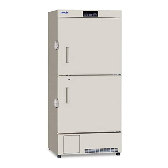
- Page 1 Operating Instructions Biomedical Freezer MDF-U5312 Please read the operating instructions carefully before using this product, and keep the operating instructions for future use. See page 28 for model number.
-
Page 3: Table Of Contents
CONTENTS INTRODUCTION P. 2 PRECAUTIONS FOR SAFE OPERATION P. 3 ENVIRONMENTAL CONDITIONS P. 7 FREEZER COMPONENTS P. 8 Control panel P. 10 INSTALLATION SITE P. 11 INSTALLATION P. 12 START-UP OF UNIT P. 13 TEMPERATURE SETTING P. 14 Key lock function P. -
Page 4: Introduction
INTRODUCTION ■ Read the operating instructions carefully before using the product and follow the instructions for safe operation. ■ PHC Corporation takes no responsibility for safety if the product is not used as intended or is used with any procedures other than those given in the operating instructions. ■... -
Page 5: Precautions For Safe Operation
PRECAUTIONS FOR SAFE OPERATION It is imperative that the user complies with the operating instructions as it contains important safety advice. Items and procedures are described so that you can use this unit correctly and safely. If the precautions advised are followed, this will prevent possible injury to the user and any other person. - Page 6 PRECAUTIONS FOR SAFE OPERATION WARNING Do not use the unit outdoors. Current leakage or electric shock may result if the unit is exposed to rain water. Only qualified engineers or service personnel should install the unit. The installation by unqualified personnel may cause electric shock or fire. Install the unit on a sturdy floor and take an adequate precaution to prevent the unit from turning over.
- Page 7 PRECAUTIONS FOR SAFE OPERATION WARNING Ensure you do not inhale or consume medication or aerosols from around the unit at the time of maintenance. These may be harmful to your health. Never splash water directly onto the unit as this may cause electric shock or short circuit. Never put containers with liquid on the unit as this may cause electric shock or short circuit when the liquid is spilled.
- Page 8 PRECAUTIONS FOR SAFE OPERATION CAUTION This unit must be plug into a dedicated circuit protected by branch circuit breaker. Use a dedicated power source as indicated on the rating label attached to the unit. A multiple-tap may cause fire resulting from abnormal heating. Connect the power supply plug to the power source firmly after removing the dust on the plug.
-
Page 9: Environmental Conditions
ENVIRONMENTAL CONDITIONS This equipment is designed to be safe at least under the following conditions (based on the IEC 61010-1): ■ Indoor use; ■ Altitude up to 2000 m; ■ Ambient temperature 5 C to 40 ■ Maximum relative humidity 80 % for temperature up to 31 C decreasing linearly to 50 % relative humidity at 40 ■... -
Page 10: Freezer Components
FREEZER COMPONENTS Space for interface board Back side... - Page 11 FREEZER COMPONENTS 1. Door: To open the door, grip the handle. When closing, lock the door latch completely. 2. Handle: Always grip the handle to open the door. 3. Lock: Turn clockwise to 180 with a key and the door is securely locked. 4.
-
Page 12: Control Panel
FREEZER COMPONENTS Control panel 1. Alarm lamp (ALARM): This lamp is flashed when the audible alarm is activated. 2. Digital temperature indicator: This indicator shows the present chamber temperature or set temperature and error code is also indicated in the event of alarm. 3. -
Page 13: Installation Site
INSTALLATION SITE To operate this unit properly and to obtain maximum performance, install the unit in a location with the following conditions: ■ A location not subjected to direct sunlight Do not install the unit under direct sunlight. Installation in a location subjected to direct sunlight cannot obtain the intended performance. -
Page 14: Installation
INSTALLATION 1. Removing the packaging materials and tapes Remove all transportation packaging materials and tapes. Open the doors and ventilate the unit. If the outside panels are dirty, clean them with a diluted neutral dishwashing detergent. (Undiluted detergent can damage the plastic components. For the dilution, refer to the instruction of the detergent.) After the cleaning with the diluted detergent, always wipe it off with a wet cloth. -
Page 15: Start-Up Of Unit
START-UP OF UNIT Use the following procedure to start trial operation or actual operation of the unit. 1. Connect the power supply cord to the dedicated outlet having appropriate rating with the chamber empty, and turn on the power switch on the freezer. 2. -
Page 16: Temperature Setting
TEMPERATURE SETTING Table 1 shows the basic procedure for setting the chamber temperature. Perform key operations in the sequence indicated in the table. The example in the table is based on the assumption that the desired temperature is -25 Note: The chamber temperature is set to -30 C at the factory. -
Page 17: Alarm Temperature Setting
ALARM TEMPERATURE SETTING This unit is provided with both high and low temperature alarms. The temperature at which the alarm is activated can be changed. The available set range for high temperature alarm is between +5 C and +15 C, and -5 C and -15 C for low temperature alarm against the set temperature. -
Page 18: Setting Of Alarm Resume Time
SETTING OF ALARM RESUME TIME The buzzer and remote alarm are cancelled by pressing buzzer stop key (BUZZER) on the control panel during alarm condition. However, if the alarm condition is continued after the “alarm resume time” has passed, the buzzer sounds again. It is possible to change the alarm resume time by the procedure shown in the Table.5. -
Page 19: Remote Alarm Terminal
REMOTE ALARM TERMINAL WARNING Always disconnect the power supply cord before connecting an alarm device to the remote alarm terminal. The remote alarm terminal is installed at the back of the unit. The alarm is outputted from this terminal. Contact capacity is DC 30 V, 2 A. Contact output: between COM. -
Page 20: Alarms & Safety Functions
ALARMS & SAFETY FUNCTIONS This unit has the alarms and safety functions shown in Table 6, and also self diagnostic functions. Table 6 Alarms and safety functions Alarm Situation Indication Alarm buzzer Safety functions If the chamber temperature is higher Alarm lamp is flashed. -
Page 21: Routine Maintenance
ROUTINE MAINTENANCE WARNING Always disconnect the power supply to the unit prior to any repair or maintenance of the unit in order to prevent electric shock or injury. Ensure you do not inhale or consume medication or aerosols from around the unit at the time of maintenance. -
Page 22: Replacement Of Battery
REPLACEMENT OF BATTERY Replace the battery for power failure alarm about every 3 years (when the battery indicator lights) to ensure the alarm is operated in the event of power failure. Contact our sales representative or agent for the replacement of battery when the battery indicator lights. ... -
Page 23: Troubleshooting
TROUBLESHOOTING If the unit malfunctions, check out the following before calling for service. Malfunction Check/Remedy ■ The circuit breaker of power source is active The chamber is not cooled ■ The voltage is too low. (In this case, call an electrician.) at all ■... -
Page 24: Disposal Of Unit
DISPOSAL OF UNIT WARNING If the unit is to be stored unused in an unsupervised area for an extended period ensure that children do not have access and doors cannot be closed completely. The disposal of the unit should be accomplished by appropriate personnel. Always remove doors to prevent accidents such as suffocation. -
Page 25: Temperature Recorder (Option)
TEMPERATURE RECORDER (OPTION) WARNING Always disconnect the power supply to the unit prior to attachment of a temperature recorder in order to prevent electric shock or injury. A temperature recorder is available for the freezer as the optional component. The type of the temperature recorder is MTR-G85C and MTR-4015LH. - Page 26 TEMPERATURE RECORDER (OPTION) 5. Slide the recording paper along the guide plate so that the recording paper will not be forced out of the date & time Notch for adjustment slot. (See Fig. 5). date & time adjustment 6. After ascertaining that the holes on the side of the recording paper are locked into the teeth of the sprocket, turn the gear and send the recording paper into the used recording paper storage.
-
Page 27: Setting Of Mtr-G85C
TEMPERATURE RECORDER (OPTION) Setting of MTR-G85C Chart guides Pen cap holder Pen arm Back-up battery Chart hub cover Pen lifter Recording paper Ink pen Paper speed selector Key lock Pilot lamp Open cover Fast feed button Power switch latch Zero adjustment screw Loading the ink pen: 1. - Page 28 TEMPERATURE RECORDER (OPTION) Starting recording and setting the time: Turn the power switch ON. The ink pen will move inward on the recording paper and stop temporarily at the 0 % position (equivalent to the 40 C line). Then the ink pen will Ink pen move to the position which indicates the measured Hour...
-
Page 29: Specifications
SPECIFICATIONS Biomedical Freezer Product name MDF-U5312 External dimensions W804 mm x D772 mm x H1802 mm Internal dimensions W658 mm x D607 mm x H1272 mm Effective capacity 482 L Exterior Painted steel Interior Styrol resin Insulation Rigid polyurethane foamed-in place... -
Page 30: Performance
PERFORMANCE Biomedical Freezer Product name MDF-U5312 Model No. MDF-U5312-PR Cooling performance C (ambient temperature; 35 C, no load) Temperature control range C to -30 Power voltage AC 220 V Rated frequency 60 Hz Rated power consumption 330 W Noise level 40 dB [A] (background noise;... -
Page 31: Safety Check Sheet
CAUTION Please fill in this form before servicing. Hand over this form to the service engineer to keep for his and your safety. Safety check sheet 1. Freezer contents : □ □ Risk of infection: □ □ Risk of toxicity: □... - Page 32 1-1-1 Sakada, Oizumi-machi, Ora-gun, Gunma 370-0596, Japan Printed in Japan LDCL033800-0 © PHC Corporation 2018 S0418-0...
Need help?
Do you have a question about the MDF-U5312 and is the answer not in the manual?
Questions and answers