
Related Manuals for Phcbi MDF-C8V1 Series


Summary of Contents for Phcbi MDF-C8V1 Series
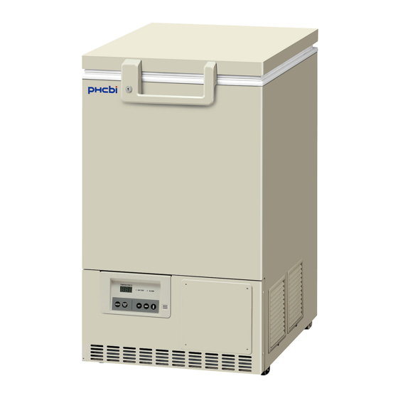
- Page 1 Operating Instructions Ultra-Low Temperature Freezer MDF-C8V1 Series Please read the operating instructions carefully before using this product, and keep the operating instructions for future use. See page 34 for all model numbers.
-
Page 3: Table Of Contents
CONTENTS INTRODUCTION P. 2 PRECAUTIONS FOR SAFE OPERATION P. 3 ENVIRONMENTAL CONDITIONS P. 7 FREEZER COMPONENTS P. 8 Control panel P. 10 INSTALLATION SITE P. 11 INSTALLATION P. 12 START-UP OF UNIT P. 13 CHAMBER TEMPERATURE SETTING P. 14 KEY LOCK FUNCTION P. -
Page 4: Introduction
INTRODUCTION ■ Read the operating instructions carefully before using the product and follow the instructions for safe operation. ■ PHC Corporation takes no responsibility for safety if the product is not used as intended or is used with any procedures other than those given in the operating instructions. ■... -
Page 5: Precautions For Safe Operation
PRECAUTIONS FOR SAFE OPERATION It is imperative that the user complies with the operating instructions as it contains important safety advice. Items and procedures are described so that you can use this unit correctly and safely. If the precautions advised are followed, this will prevent possible injury to the user and any other person. - Page 6 PRECAUTIONS FOR SAFE OPERATION WARNING Do not use the unit outdoors. Current leakage or electric shock may result if the unit is exposed to rain water. Only qualified engineers or service personnel should install the unit. The installation by unqualified personnel may cause electric shock or fire. Install the unit on a sturdy floor and take an adequate precaution to prevent the unit from turning over.
- Page 7 PRECAUTIONS FOR SAFE OPERATION WARNING Ensure you do not inhale or consume medication or aerosols from around the unit at the time of maintenance. These may be harmful to your health. Never splash water directly onto the unit as this may cause electric shock or short circuit. Never put containers with liquid on the unit as this may cause electric shock or short circuit when the liquid is spilled.
- Page 8 PRECAUTIONS FOR SAFE OPERATION CAUTION Use a dedicated power source (a dedicated circuit with a breaker) as indicated on the rating label attached to the unit. A branched circuit may cause fire resulting from abnormal heating. Connect the power supply plug to the power source firmly after removing the dust on the plug. A dusty plug or improper insertion may cause a heat or ignition.
-
Page 9: Environmental Conditions
ENVIRONMENTAL CONDITIONS This equipment is designed to be safe at least under the following conditions (based on the IEC 61010-1): ■ Indoor use; ■ Altitude up to 2000 m; ■ Ambient temperature 5 C to 40 ■ Maximum relative humidity 80 % for temperature up to 31 C decreasing linearly to 50 % relative humidity at 40 ■... -
Page 10: Freezer Components
FREEZER COMPONENTS... - Page 11 FREEZER COMPONENTS 1. Lock: By turning to 180 degree to clockwise with a key, the door can be locked. 2. Door: Hinged type. To open the door, grip the handle. 3. Door gasket: Seals the door and prevents leakage of cold air. 4.
-
Page 12: Control Panel
FREEZER COMPONENTS Control panel 1. Digital temperature indicator (TEMPERATURE): This indicator shows the present chamber temperature or set temperature. 2. Battery check lamp (BATTERY): This lamp lights to recommend the battery replacement. For the replacement, consult our sales representative or agent. 3. -
Page 13: Installation Site
INSTALLATION SITE To operate this unit properly and to obtain maximum performance, install the unit in a location with the following conditions: ■ A location not subjected to direct sunlight Do not install the unit under direct sunlight. Installation in a location subjected to direct sunlight cannot obtain the intended performance. -
Page 14: Installation
INSTALLATION 1. Removing the packaging materials and tapes Remove all transportation packaging materials and tapes. Open the doors and ventilate the unit. If the outside panels are dirty, clean them with a diluted neutral dishwashing detergent. (Undiluted detergent can damage the plastic components. For the dilution, refer to the instruction of the detergent.) After the cleaning with the diluted detergent, always wipe it off with a wet cloth. -
Page 15: Start-Up Of Unit
START-UP OF UNIT Use the following procedure to start trial operation or actual operation of the unit. 1. Check that the power switch and battery switch are OFF. 2. Turn off the power switch of the Backup cooling kit (optional component) if it is installed. 3. -
Page 16: Chamber Temperature Setting
CHAMBER TEMPERATURE SETTING Table 1 shows the basic procedure for setting the chamber temperature. Perform key operations in the sequence indicated in the table. The example in the table is based on the assumption that the desired temperature is -75 Note: The chamber temperature is set to -80 C at the factory. -
Page 17: Function Mode
FUNCTION MODE This unit has the following function mode. Indication Mode Settable range Between 5 C and 20 C higher than the Setting of high temperature alarm chamber set temperature (1 C gradient) Between -5 C and -20 C lower than the Setting of low temperature alarm chamber set temperature (1 C gradient) - Page 18 ALARM TEMPERATURE SETTING Note: The alarm temperature is set at the factory 10 C lower than the chamber set temperature. The available range of low temperature alarm is between 5 C and 20 C lower than the chamber set temperature. Table 4 Procedure for setting low temperature alarm Description of operation Key operated...
-
Page 19: Setting Of Alarm Resume Time
SETTING OF ALARM RESUME TIME The buzzer is silenced by pressing buzzer stop key (BUZZER) key on the control panel during alarm condition (The remote alarm cannot stopped.). However, if the alarm condition is continued after the “alarm resume time” has passed, the buzzer sounds again. It is possible to change the alarm resume time by the procedure shown in the Table.5. -
Page 20: Chanage Of Compressor Delay Time
CHANGE OF COMPRESSOR DELAY TIME The delay time of the compressor can be changed to reduce the load on the power line and to facilitate the start-up (reset) of the freezer after power failure. The example in the table is based on the assumption that the delay time is changed to 4 minutes. The delay time is set in 3 minutes at the factory. -
Page 21: Remote Alarm Terminal
REMOTE ALARM TERMINAL WARNING Always disconnect the power supply cord before connecting an alarm device to the remote alarm terminal. The terminal of the remote alarm is installed at the back of the unit. The alarm is output from this terminal. -
Page 22: Alarms & Safety Functions
ALARMS & SAFETY FUNCTIONS This unit has the alarms and safety functions shown in Table 7, and also self diagnostic functions. Table 7 Alarms and safety functions Alarm & Safety Situation Indication Buzzer Safety operation If the chamber temperature is higher Alarm lamp is flashed. -
Page 23: Routine Maintenance
ROUTINE MAINTENANCE WARNING Always disconnect the power supply to the unit prior to any repair or maintenance of the unit in order to prevent electric shock or injury. Ensure you do not inhale or consume medication or aerosols from around the unit at the time of maintenance. -
Page 24: Battery
ROUTINE MAINTENANCE Battery The battery for power failure alarm is an article for consumption. The battery life is approximately 3 years. The buzzer and alarm lamp cannot be activated at the power failure and the stored items may be influenced if the battery is left as it is for more than 3 years. It is recommended that the battery is replaced ahead of time. -
Page 25: Troubleshooting
TROUBLESHOOTING If the unit malfunctions, check out the following before calling for service. Malfunction Check/Remedy The freezer does not run ■ The power supply cord is not connected to the proper outlet. ■ The power source does not have enough capacity. ■... -
Page 26: Disposal Of Unit
DISPOSAL OF UNIT WARNING If the unit is to be stored unused in an unsupervised area for an extended period ensure that children do not have access and doors cannot be closed completely. The disposal of the unit should be accomplished by appropriate personnel. Always remove doors to prevent accidents such as suffocation. - Page 27 DISPOSAL OF UNIT (English) Disposal of Old Equipment and Batteries Only for European Union and countries with recycling systems These symbols on the products, packaging, and/or accompanying documents mean that used electrical and electronic products and batteries must not be mixed with general household waste. For proper treatment, recovery and recycling of old products and used batteries, please take them to applicable collection points in accordance with your national legislation.
- Page 28 DISPOSAL OF UNIT (French) L’élimination des équipements et des batteries usagés Applicable uniquement dans les pays membres de l’Union européenne et les pays disposant de systèmes de recyclage. Apposé sur le produit lui-même, sur son emballage, ou figurant dans la documentation qui l’accompagne, ce pictogramme indique que les piles, appareils électriques et électroniques usagés, doivent être séparées des ordures ménagères.
- Page 29 DISPOSAL OF UNIT (Portuguese) Eliminação de Equipamentos Usados e Baterias Apenas para a União Europeia e países com sistemas de reciclagem Estes símbolos nos produtos, embalagens, e/ou documentos que os acompanham indicam que os produtos elétricos e eletrónicos e as baterias usados não podem ser misturados com os resíduos urbanos indiferenciados.
- Page 30 DISPOSAL OF UNIT (Dutch) Het ontdoen van oude apparatuur en batterijen. Enkel voor de Europese Unie en landen met recycle systemen. Deze symbolen op de producten, verpakkingen en/of begeleidende documenten betekenen dat gebruikte elektrische en elektronische producten en batterijen niet samen mogen worden weggegooid met de rest van het huishoudelijk afval.
-
Page 31: Disposal Of Battery
DISPOSAL OF BATTERY (For service personnel only) Location of a nickel-metal-hydride battery This unit is provided a nickel-metal-hydride battery for the power failure warning device. The battery is located at the back of the control panel. (Fig. 1) The high voltage components are enclosed in the side cover. The side cover should be removed by a qualified engineer or service personnel only to prevent the electric shock. -
Page 32: Temperature Recorder (Option)
TEMPERATURE RECORDER (OPTION) WARNING Always disconnect the power supply to the unit prior to attachment of a temperature recorder in order to prevent electric shock or injury. A temperature recorder is available for the freezer as the optional component. The type of the temperature recorder is MTR-85H, MTR-G85A/MTR-G85C. -
Page 33: Backup Cooling Kit (Option)
BACKUP COOLING KIT (OPTION) This freezer can be provided with a backup cooling kit (CVK-UB4) which is available as an optional component. For the installation, refer to the instruction manual enclosed with the backup cooling kit. BACK UP STANDBY BATTERY CVK-UB4 control panel CVK-UB4 switch box 1. - Page 34 BACKUP COOLING KIT (OPTION) With the backup cooling kit (CVK-UB4), the freezer prevents the chamber temperature from going up by injecting the liquid CO when the power supply is disconnected (power failure, disconnection of power supply cord, breaker OFF) or in the case of failure of freezer itself. The liquid CO is injected with the activation of solenoid valve energized by battery when the chamber temperature reaches the temperature set by the temperature control knob.
-
Page 35: Specifications
SPECIFICATIONS Ultra-Low Temperature Freezer Product name MDF-C8V1 External dimensions W550 mm x D685 (+83)* mm x H945 mm Internal dimensions W405 mm x D490 mm x H425 mm Effective capacity 84 L Exterior Painted steel Interior Painted steel Door Painted steel Access port Diameter 17 mm, back side, bottom Cabinet;... -
Page 36: Performance
PERFORMANCE Ultra-Low Temperature Freezer Product name MDF-C8V1 MDF-C8V1-PK Model No. MDF-C8V1-PT MDF-C8V1-PA MDF-C8V1-PE MDF-C8V1-PR Cooling performance C (ambient temperature; 30 C, no load) Temperature control range C to -80 C (ambient temperature; 30 C, no load) Rated voltage AC 220 V/ 230V/ AC 110 V AC 115 V AC 220V... -
Page 37: Safety Check Sheet
CAUTION Please fill in this form before servicing. Hand over this form to the service engineer to keep for his and your safety. Safety check sheet 1. Freezer contents : □ □ Risk of infection: □ □ Risk of toxicity: □... - Page 40 1-1-1 Sakada, Oizumi-machi, Ora-gun, Gunma 370-0596, Japan Printed in Japan LDCL028500-0 © PHC Corporation 2018 S0418-0...
Need help?
Do you have a question about the MDF-C8V1 Series and is the answer not in the manual?
Questions and answers
hello how do I know what is the lowest temperature limit this freezer can be set up at?