Table of Contents
Advertisement
Quick Links
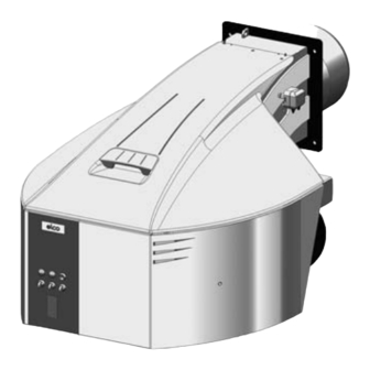
EKEVO 6/N6.2400 / EKEVO 6/N6.2900 GL-E
EKEVO 7/N7.3600 / EKEVO 7/N7.4500 GL-E
EKEVO 8/N8.5800 / EKEVO 8/N8.7100 GL-E
EKEVO 9/N9.8700 / EKEVO 9/N9.10400 GL-E
Original Operating Instructions
For authorised specialist engineers
Fuel-oil/gas dual fuel burner
de ................................................... 4200 1044 7602
fr ..................................................... 4200 1044 7702
it ..................................................... 4200 1044 7802
nl .................................................... 4200 1044 7902
EKEVO 6/EKEVO 7 GL-E ............................ 4200 1054 2400
EKEVO 8/EKEVO 9 GL-E ............................ 4200 1071 8500
N6/N7 GL-E .................................................. 4200 1044 7501
N8/N9 GL-E .................................................. 4200 1044 8600
BT300
EKEVO 6/EKEVO 7 GL-E de / en / fr ..........4201 1017 2700
EKEVO 8/EKEVO 9 GL-E de / en / fr ....................................
N6/N7 GL-E de / en / fr ........................................14 071 677
N8/N9 GL-E de / en / fr ........................................14 071 721
Etamatic ext.
EKEVO 6/EKEVO 7 GL-E de / en / fr ..........4201 1017 2700
EKEVO 8/EKEVO 9 GL-E de / en / fr ....................................
N6/N7 GL-E de / en / fr ........................................14 071 688
N8/N9 GL-E de / en / fr ........................................14 071 732
03/2016 - Art. Nr. 4200 1044 8002A
Advertisement
Table of Contents

Related Manuals for elco EKEVO 7.3600 GL-E


Summarization of Contents
General Information
Important Information
Key safety and usage guidelines for the burners.
Burner Description
Details on the design and features of the EKEVO/N6-N9 GL-E burners.
Scope of Delivery
Lists the components included with the burner upon delivery.
Installation Location
Specifies suitable and unsuitable environments for burner installation.
Notes for the Operator
Important advice for the end-user regarding system maintenance.
Transport Packaging Storage
Guidelines for safe handling, transport, and storage of the burner.
Disposal
Instructions for environmentally responsible disposal of the burner.
Installation
Air Duct Connection and Rotating Air Box
How to connect the air duct and rotate the air box for installation.
General Information Regarding Burner Installation
Covers critical aspects like tightening torques for accessories and connections.
Boiler Lining for GL-E Burner
Guidance on installing the burner lining and ensuring proper dimensions.
Burner Installation
Step-by-step instructions for physically attaching the burner to the boiler.
Combustion Components
Technical data and adjustment checks for burner combustion parts.
Combustion Components N6/N7, EKEVO 6/EKEVO 7 Data/Check
Specific adjustment data and checks for N6/N7 and EKEVO 6/7 combustion components.
Combustion Components N8/EKEVO 8 Data/Check
Specific adjustment data and checks for N8 and EKEVO 8 combustion components.
Combustion Components N9/EKEVO 9 Data/Check
Specific adjustment data and checks for N9 and EKEVO 9 combustion components.
Gas Ignition Electrodes Adjustment Data/Check
Guidelines for adjusting and checking gas ignition electrodes.
Fuel-Oil Ignition Electrodes Adjustment Data/Check
Guidelines for adjusting and checking fuel-oil ignition electrodes.
Gas Train
Information about gas supply lines and their components.
Description of Gas Train with VGD
Details on gas trains using Siemens VGD double valves and their specifications.
Description of Gas Train with MBC
Details on gas trains using Dungs MBC double gas valves.
Basic Design
Diagrams illustrating low and high pressure gas train configurations.
Fuel-Oil System Diagram
Visual representation of the fuel-oil supply and return systems.
Fuel-Oil Pressure Switch
Information on installing and setting the fuel-oil pressure switch.
Gas Train Components
Double Gas Valve VGD with SKP Servo Motors
Details on VGD double gas valves and their SKP actuators.
Double Gas Valve MBC (Gas Multiblock)
Technical specifications and features of the MBC gas multiblock.
Overview of Electrical Connection
Wiring diagrams for MBC-300-1200 SE and MBC-1900-7000 SE.
Replacing the MBC-300-700-1200 Filter
Procedure for replacing the filter element in the MBC gas multiblock.
Adjusting the MBC-300-700-1200-SE Pressure Regulation Component
Steps for adjusting the pressure regulation component of the MBC multiblock.
Adjusting the MBC-1900-7000-SE Pressure Regulation Component
Procedure to adjust the pressure regulation component of the MBC 1900-7000 SE.
Gas Filter
Installation, mounting, and replacement instructions for the gas filter.
Test Burner
Purpose and technical data of the test burner used in gas trains.
Gas Pressure Switch
Information on gas pressure switches, their settings, and certification.
Pressure Switch
Air Pressure Switch
Details on the air pressure switch, its function, and adjustment.
Hydraulics
General Information Regarding the Fuel-Oil System
Overview of the fuel-oil system's general principles and diagrams.
Fuel-Oil Hydraulics Diagram
Schematic illustrating the fuel-oil hydraulic circuit for different burner models.
Commissioning
General Information Regarding the Fuel-Oil System
General guidelines for commissioning the fuel-oil system.
Fuel-Oil Connection
Procedures for connecting fuel-oil lines, including hoses and valves.
Shut-off Valve
Requirements for installing manual shut-off valves in fuel-oil supply lines.
Gas and Air Separators
Importance of fitting gas/air separators in the fuel supply line.
Fuel-Oil Filter
Recommendation for installing a fuel-oil filter upstream of the pump.
Installation Options
Describes two-line and ring-line installation options for fuel-oil systems.
Fuel-Oil Pressure Regulator (Supply Line)
How to set the fuel-oil pressure regulator for optimal supply pressure.
Venting
Procedure for venting the fuel-oil pump and hydraulic system.
Pressure Regulation (Fuel-Oil Intake Pressure)
Maximum permissible vacuum for fuel-oil intake and its implications.
Connecting Test Devices
Guidance on connecting test gauges for pressure and intake measurements.
Pump Type TA
Application, functions, and technical data of the TA fuel-oil pump.
Fuel-Oil Hydraulic Block
Functionality and maintenance of the integrated fuel-oil hydraulic block.
Return Nozzle Rod RDN
Description and function of the RDN return nozzle rod.
Nozzle Selection, Type W2 - 45°/50°
Diagram and guidance for selecting W2-type nozzles based on oil pressure.
Allocation of Nozzle - W2 - 45°/50°
Table mapping W2 nozzles to power output and control shaft size.
Return Nozzle Rod RDG
Description and function of the RDG return nozzle rod.
Nozzle Selection, Type Sonic 60°
Diagram for selecting Sonic 60° nozzles based on return pressure.
Allocation of Nozzle - Sonic 60°
Table mapping Sonic 60° nozzles to power and control shaft size.
Nozzle Selection, Type Sonic 45°
Diagram for selecting Sonic 45° nozzles based on return pressure.
Allocation of Nozzle - Sonic 45°
Table mapping Sonic 45° nozzles to power and control shaft size.
Burner Control Unit
Information on the BT340 electronic burner controller and its functions.
Electrical Cabinet Door Construction
Overview of controls and indicators on the electrical cabinet doors.
Servomotor STE
Technical data and function of the STE4.5 servomotor.
Servomotor STM 40
Technical data and function of the STM 40 servomotor.
Flame Sensor
Types of flame sensors used and their connection/operation.
Gas Fitting Connection
Guidelines for connecting the gas fitting to the burner.
Electrical Connection
Procedures and safety notes for electrical connections.
Checks Before Commissioning
Essential checks to perform before initial system commissioning.
Gas Connection
Standards and procedures for installing and operating gas connections.
Fuel-Air Compound Control
How the compound control system regulates fuel and air for optimal combustion.
Burner Power Adjusting Sequence
Step-by-step guide for adjusting burner power settings.
Inspection
Procedures for inspecting the system before commissioning.
Preventilation
Importance and calculation of preventilation air rates for the burner.
Fuel-Oil Start-Up Mode
Process for starting up the burner in fuel-oil mode.
Fuel-Oil Operating Mode
How the burner operates after successful start-up in fuel-oil mode.
General Safety Functions
Key safety features and fault handling procedures for fuel-oil operation.
Gas Start-Up Mode
Process for starting up the burner in gas mode.
Gas Operating Mode
How the burner operates after successful start-up in gas mode.
General Safety Functions
Key safety features and fault handling procedures for gas operation.
Servicing
Maintenance
General recommendations and requirements for burner and boiler servicing.
Replacing the Control Unit
Instructions for replacing the electronic control unit (Burnertronic).
Checking the Combustion Components
Steps for checking and maintaining the burner's combustion components.
Cleaning the Fan
Procedure for cleaning the fan wheel and housing.
Checking / Installing the Combustion Components
Detailed steps for checking and installing combustion components.
Checking the Flue Gas Temperature
How to measure and check flue gas temperature at regular intervals.
EKEVO 6/EKEVO 7 Rotation Procedure of Air Box
Guide for rotating the air box on EKEVO 6/7 burners.
EKEVO 8/EKEVO 9 Rotation Procedure of Air Box
Guide for rotating the air box on EKEVO 8/9 burners.
Fan Wheel Setting
Instructions for setting and installing the fan wheel.
Exhaust Gas Measurements
Procedures for measuring exhaust gas and calculating efficiency.
Diagnosing and Remedying Faults
Guide to identifying and fixing common burner faults and issues.
Faults
General advice on troubleshooting system faults and safety procedures.
Need help?
Do you have a question about the EKEVO 7.3600 GL-E and is the answer not in the manual?
Questions and answers