
Related Manuals for Lumiax MT3075


Summary of Contents for Lumiax MT3075
- Page 1 1.03.02.10029-1-1 Magic series MPPT Solar Controller 12/24/48V,10/15/20/30/40A, 130/200/260/390/520/780W, 1KW/2KW MENU User Manual User Manual_Magic series_MF CE, Rohs, ISO9001:2015 Subject to change without notice!
-
Page 2: Table Of Contents
Safety instructions and waiver of liability....................2 Safety Instructions ................................2 1.2 Liability Exclusion................................2 Pruduct Overview ............................3 Dimensions ..............................4 3.1 The dimensions of MT1050/1550-EU/MT1050-RS485 ................4 3.2 The dimensions of MT2075/2010/3075.......................5 3.3 The dimensions of MT3010/4010..........................6 3.4 The dimensions of MT4015 ............................7 Structure & Accessor y ..........................8 Structure &... -
Page 3: Safety Instructions And Waiver Of Liability
Dear Clients, Thank you for purchasing our Magic Series Solar PV Charge Controller Your support and trust in us are much appreciated. Please take time to read this manual this will help you make full use of the many advantages this controller can provide your PV System with This manual presents important recommendations for installing... - Page 4 2, Over view Magic series solar controller is based on an advanced maximum power point tracking (MPPT) technology developed, dedicated to the solar system, the controller conversion efficiency up to 98%. It comes with a number of outstanding features, such as: A combination of multiple tracking algorithms enables tracking the maximum power point quickly and accurately Innovative Max Power Point Tracking(MPPT) technology, tracking efficiency >99.9%...
- Page 5 High Voltage Strings and Grid-Tie Modules Another benefit of MPPT technology is the ability to charge batteries with solar arrays of higher nominal voltages. For example, a 12 Volt battery bank may be charged with a 12-, 24-, 36-, or 48-Volt nominal off-grid solar array.
- Page 6 2.3 MPPT—Four Charging Stages Magic series controller has a 4-stage battery charging algorithm for rapid, efficient, and safe battery charging. U(V) Equalize Charge 14.8V 14.5V 13.7V Night MPPT Boost Float Night Charge Charge Charge TIME MPPT Charge In this stage, the battery voltage has not yet reached boost voltage and 100% of available solar power is used to recharge the battery.
-
Page 7: Dimensions
3, Dimensions 3.1 The dimensions of MT1050/1550-EU/MT1050-RS485 Unit:mm MT1050/1550-EU Φ4.5 13.5 MT1050-RS485... -
Page 8: The Dimensions Of Mt2075/2010/3075
3.2 The dimensions of MT2075/2010/3075 Unit:mm 58 MT2075 64 MT2010/3075 24.25 Φ4.5 MENU MT2075 MT2010/3075... -
Page 9: The Dimensions Of Mt3010/4010
3.3 The dimensions of MT3010/4010 Unit:mm MT4010 MT3010 Φ4.5 MENU MT3010 MT4010... -
Page 10: The Dimensions Of Mt4015
3.4 The dimensions of MT4015 Unit:mm Φ4.5 MENU 11.05... -
Page 11: Structure & Accessor Y
4, Structure & Accessor y Structure & Characteristics of MT1050/1550-EU/MT1050-RS485 ①Heat Sink —dissipate controller heat ②Plastic Case ③ —Internal protection ③LCD —Display settings and operating status, system parameters ④ ④Key: MENU、OK —Set and view the operating parameters ⑤Temperature Sensor Port ⑨... -
Page 12: Structure & Characteristics Of Mt2075/2010/3075
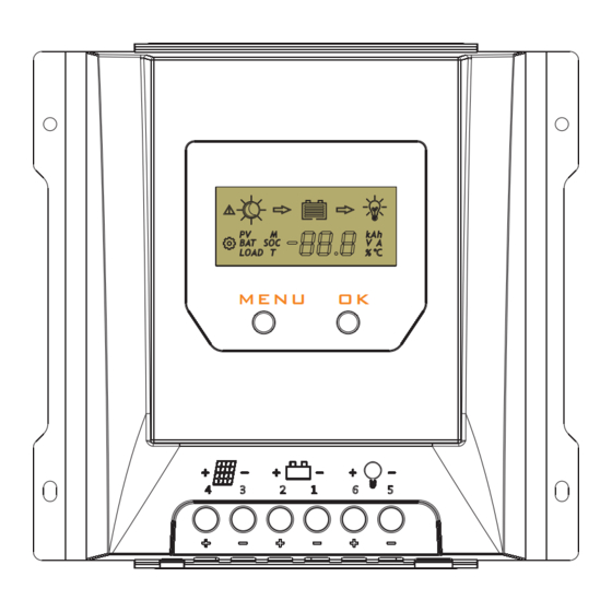
Structure & Characteristics of MT2075/2010/3075 ①Heat Sink —dissipate controller heat ②Plastic Case —Internal protection ③LCD ③ — Display settings and operating status, system parameters MENU ④Key: MENU、OK —Set and view the operating parameters ⑤RJ11 interface ④ —Connecting monitoring devices ⑥Temperature Sensor Port —Collect temperature information, Temperature compensation. -
Page 13: Temperature Sensor
Structure & Characteristics of MT3010/4010/4015 ①Heat Sink —dissipate controller heat ②Plastic Case —Internal protection ③LCD — Display settings and operating status, system parameters ④Key: MENU、OK ③ —Set and view the operating parameters ⑤RJ11 interface MENU —Connecting monitoring devices ⑥Temperature Sensor Port —Collect temperature information, the Temperature compensation. -
Page 14: Rs485
4.5 Rs485 MT1050-RS485 refer to figure 1 for interface RS485 port with RJ11 interface controller. The interface definition is shown in Figure 2: Pin No. Definition 1 2 3 4 5 6 RS485-A RS485-B RJ11 for controller figure 2 figure 1 Please contact the sales for the latest version of the communication protocol. -
Page 15: Installation
5, Installation CAUTION: Please read all instructions and precautions in the manual before proceeding with the installation It is recommended to remove the protective film cover from the LCD screen before operation 5.1 Installation Notes ⑴ This charge controller must only be used in PV systems by requirements given in this user manual and the specifications of other system components provided by their manufacturers. -
Page 16: Wiring Specifications
Rated Solar wire Batter y wire Load wire Rated charging Model discharging diameter diameter diameter current current (mm²/AWG) (mm²/AWG) (mm²/AWG) MT1050-EU/RS485 2.5/13 2.5/13 2.5/13 MT1550-EU 4/11 4/11 2.5/13 MT2075/2010 5/10 5/10 5/10 MT3075/3010 MT4010/4015 10/8 10/8 The indicated cable/wire sizes are for reference only. -
Page 17: Grounding
WARNING: The PV-module/array can produce open-circuit voltages in excess of 100 Vdc when exposed to sunlight. Pay highest attention to this fact. WARNING: Risk of explosion! In case the battery's positive and negative terminals or leads get ever in touch, i.e. short-circuited, a fire or explosion hazard might get triggered. Always pay maximum when handling batteries and related circuits. -
Page 18: Operation
6, Operation 6.1 LCD Display 6.1.1 Status Description Item Icon Status Daytime, not charging Daytime, charging PV array Night PV voltage、 current and ampere hours The total charge ampere hours of the solar panel Batter y capacity Batter y voltage( Set Charging target voltage for lithium batter y) Batter y current... - Page 19 6.1.2 The interface automatically cycles in the displayed sequence 6.1.3 Press OK to browse the interface...
-
Page 20: Key Function
6.1.4 Fault indication Status Icon Description Load off, fault icon display, load icon flashes, Short circuit the LCD screen displays E1 Load off, fault icon display, load icon flashes, Over current the LCD screen displays E2 Batter y level shows empty, fault icon display, Low voltage batter y frame flashes, the LCD screen displays E3 Batter y level shows full, fault icon display,... -
Page 21: Parameters Setting
6.4 Parameters setting When the icon appears in the display interface, it means that the parameters can be set. Press the MENU key for 1s, then icon flashes, press OK to change the parameter. 6.4.1 Charging target voltage(Lithium) If the batter y type is set to lithium batter y the LCD display interface is shown in the left figure Long press the MENU key for 1 second... - Page 22 6.4.4 Batter y type When the LCD shows as displayed at left, press the MENU key for 1s,the icon flashes , you can set the batter y type. Display Batter y type GEL(Default) Liquid Lithium 1.Charging Voltage Parameters(Liquid, GEL, AGM) When choosing Liquid, GEL or AGM for battery type, the parameters of boost, equalization and float...
-
Page 23: Troubleshooting
2.Street lamp Function When the load is set to Dusk to Dawn or Evening mode, the Day/Night threshold voltage and the Day/Night delay t can be set b the mobile phone APP, RS485 or Wechat APP, and the load can be turned on or off by the test function during the day charging process. -
Page 24: Protection
7.2 Protection Protection Description The controller will limit charging power to the rated level. PV Over Current Over-sized PV array will not be able to operate at the maximum power point. When PV short circuit occurs, the controller will stop charging. Remove it to resume normal operation. -
Page 25: Technical Data
8, Technical Data Item MT1050-EU MT1050-RS485 MT1550-EU System Voltage Max Charging Current MPPT Charging Voltage before boost or equalization charging stage Boost Voltage 14.5V@25℃ Equalization Voltage 14.8V@25℃(Liquid ,AGM) Batter y Float Voltage 13.7V@25℃ Parame- Low Volt. Disconnect 10.8~11.8V, SOC1~5(default:11.2V) ters 15.5V... - Page 26 Item Mt2010 MT3010 MT2075 MT3075 Max Charging Current System Voltage 12V/24V automatical recognization MPPT Charging Voltage before boost or equalization charging stage Boost Voltage 14.0~14.8V/28.0~29.6V @25℃(default:14.5/29V) Equalization Voltage 14.0~15.0V/28.0~30.0V @25℃(default:14.8/29.6V) Float Voltage 13.0~14.5V/26.0~29.0V @25℃(default:13.7/27.4V) Low voltage disconnect 10.8~11.8V/21.6~23.6V, SOC1~5(default: 11.2/22.4V) Batter y Low voltage reconnect 11.4~12.8V/22.8~25.6V(default: 12.0/24.0V)
- Page 27 Item Mt4010 Max Charging Current System Voltage 12V/24V automatical recognization MPPT Charging Voltage before boost or equalization charging stage Boost Voltage 14.0~14.8V/28.0~29.6V @25℃(default:14.5/29V) Equalization Voltage 14.0~15.0V/28.0~30.0V @25℃(default:14.8/29.6V) Float Voltage 13.0~14.5V/26.0~29.0V @25℃(default:13.7/27.4V) Low voltage disconnect 10.8~11.8V/21.6~23.6V, SOC1~5(default: 11.2/22.4V) Batter y Low voltage reconnect 11.4~12.8V/22.8~25.6V(default: 12.0/24.0V) Parame- Overcharge Protect...
- Page 28 Item Mt4015 Max Charging Current System Voltage 24V/48V automatical recognization MPPT Charging Voltage before boost or equalization charging stage Boost Voltage 28.0~29.6V/56.0~59.2V @25℃(default:29.0/58.0V) Equalization Voltage 28.0~30.0V/56.0~60.0V @25℃(default:29.6/59.2V) Float Voltage 26.0~29.0V /52.0~58.0V@25℃(default:27.4/54.8V) Low voltage disconnect 21.6~23.6V/43.2~47.2V,SOC1~5(default: 22.4/44.8V) Batter y Low voltage reconnect 22.8~25.6V/45.6~51.2V(default: 24.0/48.0V) Parame- Overcharge Protect...
- Page 29 9.Conversion Efficiency Cur ves Test conditions:Illumination intensity: 1000W/m² Temperature: 25℃ Model:MT1050-EU/MT1050-RS485 Conversion Efficiency Curves Solar Module MPP Voltage 18V/36V Vmp=18V Vmp=36V 120 130 Charging Power(W) Model:MT1550-EU Conversion Efficiency Curves Solar Module MPP Voltage 18V Vmp=18V Charging Power(W)
- Page 30 Model:MT2075、MT2010 Conversion Efficiency Curves Solar Module MPP Voltage 18V/36V Charging Power(W) Conversion Efficiency Curves Solar Module MPP Voltage 36V/54V/72V Charging Power(W)
- Page 31 Model:MT3075、MT3010 Conversion Efficiency Curves Solar Module MPP Voltage 18V/36V Charging Power(W) Conversion Efficiency Curves Solar Module MPP Voltage 36V 54V/72V Charging Power(W)
- Page 32 Model:MT4010 Conversion Efficiency Curves Solar Module MPP Voltage 18V/36V Charging Power(W) Conversion Efficiency Curves Solar Module MPP Voltage 36V 54V/72V 1040 Charging Power(W)
- Page 33 Model:MT4015 Conversion Efficiency Curves Solar Module MPP Voltage 36V 54V/72V 1000 Charging Power(W) Conversion Efficiency Curves Solar Module MPP Voltage 72V 90V 1050 1200 1350 1500 1650 1800 2000 Charging Power(W)
Need help?
Do you have a question about the MT3075 and is the answer not in the manual?
Questions and answers