Advertisement
TRACKSO CONNECTION MANUAL FOR LUMIAX CHARGE CONTROLLER
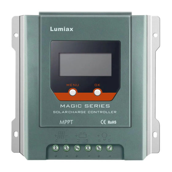
Brand:
LUMIAX
Type:
Solar Charge Controller
Models: MT2010, MT2075, MT3075BT, MT3010, MT4010, MT4015, MT6020-Pro
CONNECTION DIAGRAM
The communication terminals (RS485) are located at the bottom side of the charge controller
Connection Steps
1. Create RJ11 wire as per pinout mentioned in photo L1.
2. The charger is equipped with a RS485 port with RJ11 sockets, the
RJ11 interface is defined as mentioned in Figure L1
3. The communication terminals is located at the bottom of the
section as shown in Figure L1
4. Connect the cables to the RS485 bus terminal blocks.
5. Please make the connections from the Terminal Block chip to
TrackSo IoT Gateway as mentioned in the Table – TL1
Figure L2 – Lumiax RS485 chip connections with TrackSo IoT Gateway
Figure L1 – LUMIAX Charge Controller RS485 Port
Controller Pin No.
TrackSo Pin No.
& Assignment
3
A
4
B
Table-TL1
& Assignment
3
D+
4
D-
Advertisement
Table of Contents

Related Manuals for Lumiax MT2010


Summary of Contents for Lumiax MT2010
- Page 1 4. Connect the cables to the RS485 bus terminal blocks. 5. Please make the connections from the Terminal Block chip to TrackSo IoT Gateway as mentioned in the Table – TL1 Figure L2 – Lumiax RS485 chip connections with TrackSo IoT Gateway...
- Page 2 Data Bits: 8 , Stop Bit: 1 , Parity: None CONFIGURATION AT THE CONTROLLER END Charge Controller is available at Id,1 and baud rate-9600bps and protocol – Modbus RTU by default. NOTE: The above details are mentioned in the Installation & Operation Manual for Lumiax Solar Charge Controller...
Need help?
Do you have a question about the MT2010 and is the answer not in the manual?
Questions and answers