Sign In
Upload
Download
Table of Contents
Contents
Add to my manuals
Delete from my manuals
Share
URL of this page:
HTML Link:
Bookmark this page
Add
Manual will be automatically added to "My Manuals"
Print this page
×
Bookmark added
×
Added to my manuals
Manuals
Brands
Lumiax Manuals
Controller
Magicube Series
User manual
Lumiax Magicube Series User Manual
Mppt solar controller
Hide thumbs
1
Table Of Contents
2
3
4
5
6
7
8
9
10
11
12
13
14
15
16
17
18
19
20
21
22
23
page
of
23
Go
/
23
Contents
Table of Contents
Troubleshooting
Bookmarks
Table of Contents
Table of Contents
1 Safety Instructions and Waiver of Liability
Safety Instructions
Liability Exclusion
2 Pruduct Overview
3 Dimensions
The Dimensions of MC2010
The Dimensions of MC4010
4 Structure & Accessor y
Structure & Characteristics of MC2010
Structure & Characteristics of MC4010
Temperature Sensor
Rs485
Optional Accessories
5 Installation
Installation Notes
Mounting Location Requirements
Wiring Specifications
Connection
Grounding
6 Operation
LED Indicator
Key Function
LCD Display
Parameters Setting
7 Protections, Troubleshooting and Maintenance
Trouble Shooting
Protection
Maintenance
8 Technical Data
Advertisement
Quick Links
1
Rs485
2
Led Indicator
3
Connection
4
Parameters Setting
5
Technical Data
Download this manual
www.lumiax.com
1.03.02.10043-1
Lumiax
Magic your solar life
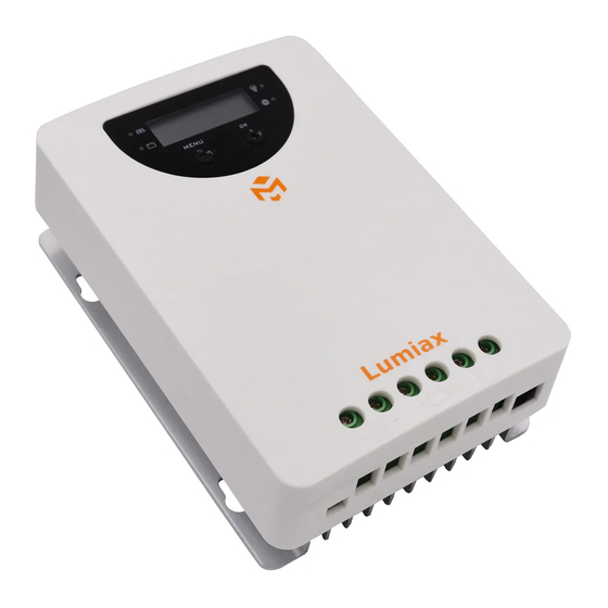
Magicube series
MPPT Solar Controller
12/24V,20/40A,
260/520/1KW
User Manual
User Manual_Magicube series_KE
CE, Rohs, ISO9001:2015
Subject to change without notice!
Table of
Contents
Previous
Page
Next
Page
1
2
3
4
5
Advertisement
Table of Contents
Need help?
Do you have a question about the Magicube Series and is the answer not in the manual?
Ask a question
Questions and answers
Related Manuals for Lumiax Magicube Series
Controller Lumiax MC2010 User Manual
Mppt solar controller (23 pages)
Controller Lumiax MC4010 User Manual
Mppt solar controller (23 pages)
Controller Lumiax Magic Series User Manual
Mppt solar controller (33 pages)
Controller Lumiax MT1050 User Manual
Mppt solar controller (33 pages)
Controller Lumiax MT2010 Connection Manual
Solar charge controller (2 pages)
Controller Lumiax MPPT Series Manual
Solar charge controller (7 pages)
Controller Lumiax MPPT-DC Series User Manual
Solar charge controller with led driver built-in (9 pages)
Controller Lumiax MPPT-DC Series User Manual
Solar charge controller with led driver built-in (6 pages)
Controller Lumiax MT3075 User Manual
Mppt solar controller (33 pages)
Controller Lumiax Smart-DC Series User Manual
Solar charge controller (9 pages)
Controller Lumiax Smart CC Series User Manual
Solar charge controller suitable for lithium battery (constant current, buck) (6 pages)
Controller Lumiax Smart-DC Series User Manual
Solar charge controller suitable for lithium battery (8 pages)
Controller Lumiax Smart Series User Manual
Solar charge controller 12v (6 pages)
Controller Lumiax Shine -EU Series User Manual
Solar charge controller 10a/15a (6 pages)
Controller Lumiax SMR1012-DCN5LIG User Manual
Solar charge controller (9 pages)
Controller Lumiax Win-NBT Series User Manual
Solar charge controller (17 pages)
This manual is also suitable for:
Mc2010
Mc4010
Table of Contents
Save PDF
Print
Rename the bookmark
Delete bookmark?
Delete from my manuals?
Login
Sign In
OR
Sign in with Facebook
Sign in with Google
Upload manual
Upload from disk
Upload from URL


Need help?
Do you have a question about the Magicube Series and is the answer not in the manual?
Questions and answers