Table of Contents

Related Manuals for Citronic CSL-14


Summarization of Contents
Introduction and Safety
Introduction to CSP/CSL Consoles
Welcome to the CSP/CSL mixing console, designed for professional and reliable sound reinforcement.
Package Contents
Lists the included items: CSP/CSL console, mains lead(s), and user manual.
General Warnings and Safety
Covers risks like electric shock, moisture, vibration, and proper earthing.
Placement and Cleaning
Advises on optimal placement, avoiding sunlight and dust, and safe cleaning methods.
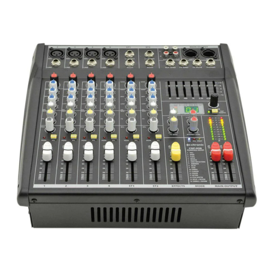
Console Layout and Input Stage
Console Layout Description
Explains the division into input and master sections and the signal path stages.
Mic/Line Input Connectivity
Details XLR and 6.3mm jack connections for microphone and line level signals.
Gain Control Function
Trims input signal level for optimal channel strip circuitry and prevents overload.
Channel Processing and Faders
EQ Section Controls
Describes the HIGH, MID, and LOW controls for adjusting audio frequencies.
Channel Routing Options
Explains controls for routing signals to AUX SEND, FX SEND, and stereo outputs.
Channel Fader and Monitoring
Details the PEAK LED, PFL function, and the 60mm channel fader for level adjustment.
Master Section and Effects
Graphic Equalizer
Details the stereo 7-band graphic equalizer for audio spectrum shaping.
DSP Effects Engine Operation
Explains controls for selecting and adjusting internal 24-bit DSP audio effects.
DSP Effects Table
Lists available programs, parameters, and their min/max values for DSP effects.
Master Output and Routing
Details main outputs, 2-track connections, and master routing controls.
Hardware and Specifications
Rear Panel Connections
Describes speaker outputs, cooling fan vent, power switch, and mains inlet.
Powering Up and Phantom Power
Instructions for powering the unit and enabling +48V phantom power.
Connecting Speakers
Guidance on connecting speakers, ensuring correct impedance and load.
Technical Specifications
Provides detailed technical data, dimensions, and power ratings for the models.
Troubleshooting and Disposal
Troubleshooting Common Issues
Addresses common problems like no power, no output, distortion, and feedback.
Block Diagram
Schematic representation of the internal signal flow and connections.
Product Disposal
Information on the proper disposal of electrical and electronic equipment.
Need help?
Do you have a question about the CSL-14 and is the answer not in the manual?
Questions and answers