Sign In
Upload
Download
Table of Contents
Contents
Add to my manuals
Delete from my manuals
Share
URL of this page:
HTML Link:
Bookmark this page
Add
Manual will be automatically added to "My Manuals"
Print this page
×
Bookmark added
×
Added to my manuals
Manuals
Brands
Citronic Manuals
Music Mixer
CSP Series
User manual
Citronic CSP Series User Manual
Mixing consoles
Hide thumbs
1
2
3
4
5
6
7
8
9
10
11
12
Table Of Contents
13
page
of
13
Go
/
13
Contents
Table of Contents
Troubleshooting
Bookmarks
Table of Contents
Console Layout
Channel Routing
Channel Faders
Graphic Equalizer
Master Output Section
Master Routing Section
Rear Panel
Phantom Power
Specifications
Troubleshooting
Advertisement
Quick Links
1
Console Layout
2
Channel Routing
3
Rear Panel
Download this manual
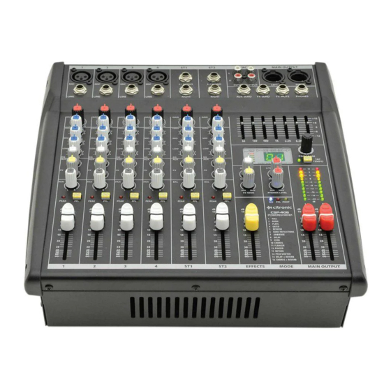
CSP & CSL-SERIES
MIXING CONSOLES
Item ref: 170.841UK, 170.843UK, 170.845UK,
170.851UK, 170.853UK, 170.855UK
User Manual
Version 2.1
Caution: Please read this manual carefully before operating
Damage caused by misuse is not covered by the warranty
Table of
Contents
Previous
Page
Next
Page
1
2
3
4
5
Advertisement
Table of Contents
Need help?
Do you have a question about the CSP Series and is the answer not in the manual?
Ask a question
Questions and answers
Related Manuals for Citronic CSP Series
Music Mixer Citronic CDM10:4 User Manual
19” 4 channel usb mixer (8 pages)
Music Mixer Citronic CDM4:2USB Owner's Manual
Professional dj mixer (8 pages)
Music Mixer Citronic CM-DSP 170.830UK User Manual
Cm-dsp compact mixers (8 pages)
Music Mixer Citronic CDMX-3 Instruction Manual
Double cd player & mixer with dsp (32 pages)
Music Mixer Citronic 172.775UK User Manual
Rackmount dj mixer (7 pages)
Music Mixer Citronic CSX-18 User Manual
(11 pages)
Music Mixer Citronic CM4-BT User Manual
Compact mixer with bluetooth (5 pages)
Music Mixer Citronic CSL Series User Manual
Mixing consoles (13 pages)
Music Mixer Citronic CSL-8 User Manual
Mixing consoles (13 pages)
Music Mixer Citronic CSL-10 User Manual
Mixing consoles (13 pages)
Music Mixer Citronic CSL-14 User Manual
Mixing consoles (13 pages)
Music Mixer Citronic CDM8:4 USB User Manual
(11 pages)
Music Mixer Citronic CMA Series User Manual
Compact mixers with fx/bt/usb (8 pages)
Music Mixer Citronic CMB-10 User Manual
Compact mixer with fx/bt/usb (10 pages)
Music Mixer Citronic 170.840UK User Manual
Csp series, csl-series (13 pages)
Music Mixer Citronic MP-X10 Owner's Manual
Mp-x10 dual usb mp3 player+digital mixer (26 pages)
This manual is also suitable for:
Csl series
Csp-408
Csp-410
Csp-714
Csl-8
Csl-10
...
Show all
Csl-14
170.841uk
170.843uk
170.845uk
170.851uk
170.853uk
170.855uk
Table of Contents
Print
Rename the bookmark
Delete bookmark?
Delete from my manuals?
Login
Sign In
OR
Sign in with Facebook
Sign in with Google
Upload manual
Upload from disk
Upload from URL


Need help?
Do you have a question about the CSP Series and is the answer not in the manual?
Questions and answers