Table of Contents
Advertisement
Quick Links
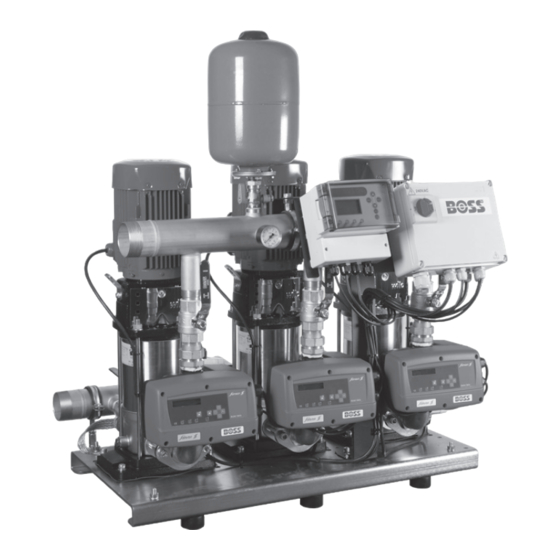
BOSS™ 1-3HELIX V....
EN
Installation and operating instructions
80460601
80460612
80460623
80460634
80460645
80460656
80460667
80460678
80460689
80460708
80460719
80460730
80460741
80460752
80460763
80460774
80460785
80460796
BOSS 1HELIX V406
BOSS 1HELIX V408
BOSS 1HELIX V605
BOSS 1HELIX V608
BOSS 1HELIX V1004
BOSS 1HELIX V1006
BOSS 2HELIX V406
BOSS 2HELIX V408
BOSS 2HELIX V605
BOSS 2HELIX V608
BOSS 2HELIX V1004
BOSS 2HELIX V1006
BOSS 3HELIX V406
BOSS 3HELIX V408
BOSS 3HELIX V605
BOSS 3HELIX V608
BOSS 3HELIX V1004
BOSS 3HELX V1006
Advertisement
Table of Contents

Related Manuals for Wilo BOSS 3HELIX V1004


Summarization of Contents
General Safety and Operation
Safety Precautions and Compliance
Details safety measures, qualified personnel requirements, and operational guidelines to prevent hazards.
Warning Symbols and Risks
Explains danger symbols, warning signals, and risks associated with non-compliance.
Transport and Storage
Storage Guidelines
Specifies environmental conditions and handling for storing the booster sets.
Transport Procedures
Handling and Transit
Outlines methods for transporting the booster, including packaging and checks for transit damage.
System Description and Operation
Control Device Overview
Describes the core automation system, including sensors and frequency inverters.
Operating Modes Explained
Details automatic and manual operation for 1, 2, and 3 pump systems.
Key Operational Features
Covers fault contacts and low water protection features.
Advanced Operation and Installation
Dry Run and Master/Slave Functions
Explains dry run protection, automatic restart attempts, and master/slave pump cycling.
Installation Site and Connections
Guides on selecting a site, making hydraulic and electrical connections.
Commissioning and Maintenance
Details initial system setup, recommended checks, and routine maintenance.
Warranty Information
Warranty Claims and Support
Provides contact details for warranty terms, claims, and aftersales support.
System Diagrams and Controls
Control Box Diagram
Visual representation of the control box for 2 and 3 pump units.
Electronic Control Drive Interface
Illustrates the main control drive unit and its operational buttons and indicators.
System Schematics
Speedcentre Controller Diagram
Shows the Speedcentre controller used in 3-pump configurations.
Pump Hydraulic Schematics
Displays the hydraulic layout and components for the pump systems.
Electrical Wiring Schematics
1-Pump System Wiring
Provides the detailed electrical wiring schematic for a single pump setup.
Electrical Wiring Schematics
2-Pump System Wiring
Provides the detailed electrical wiring schematic for a two-pump setup.
Electrical Wiring Schematics
3-Pump System Wiring
Provides the detailed electrical wiring schematic for a three-pump setup.
System Configuration Parameters
Drive Settings Menu
Lists and explains system settings configurable via the drive's menu.
Speedcentre Settings Menu
Details system settings accessible through the Speedcentre controller.
Troubleshooting and Faults
Drive Fault Codes and Solutions
Lists error codes, their causes, and troubleshooting steps for drive issues.
Troubleshooting and Specifications
General Booster Troubleshooting
Covers common symptoms, potential causes, and recommended actions for system issues.
Maximum Current Specifications
Details the maximum current ratings for various BOSS booster pump configurations.
Spare Parts Information
Spare Parts Catalog
Lists spare parts, their article numbers, and compatibility with BOSS booster models.
Regulatory Compliance
EC Declaration of Conformity
States compliance with relevant EU directives and harmonized standards for the product series.
Need help?
Do you have a question about the BOSS 3HELIX V1004 and is the answer not in the manual?
Questions and answers