Table of Contents
Advertisement
Quick Links
BOSS™ 1-3HELIX V....
EN
Installation and operating instructions
80460601
80460612
80460623
80460634
80460645
80460656
80460667
80460678
80460689
80460708
80460719
80460730
80460741
80460752
80460763
80460774
80460785
80460796
BOSS 1HELIX V406
BOSS 1HELIX V408
BOSS 1HELIX V605
BOSS 1HELIX V608
BOSS 1HELIX V1004
BOSS 1HELIX V1006
BOSS 2HELIX V406
BOSS 2HELIX V408
BOSS 2HELIX V605
BOSS 2HELIX V608
BOSS 2HELIX V1004
BOSS 2HELIX V1006
BOSS 3HELIX V406
BOSS 3HELIX V408
BOSS 3HELIX V605
BOSS 3HELIX V608
BOSS 3HELIX V1004
BOSS 3HELX V1006
Advertisement
Table of Contents

Subscribe to Our Youtube Channel
Related Manuals for Wilo BOSS 1-3HELIX V Series


Summary of Contents for Wilo BOSS 1-3HELIX V Series
- Page 1 BOSS™ 1-3HELIX V..Installation and operating instructions 80460601 BOSS 1HELIX V406 80460612 BOSS 1HELIX V408 80460623 BOSS 1HELIX V605 80460634 BOSS 1HELIX V608 80460645 BOSS 1HELIX V1004 80460656 BOSS 1HELIX V1006 80460667 BOSS 2HELIX V406 80460678 BOSS 2HELIX V408 80460689 BOSS 2HELIX V605 80460708 BOSS 2HELIX V608...
-
Page 2: Installation
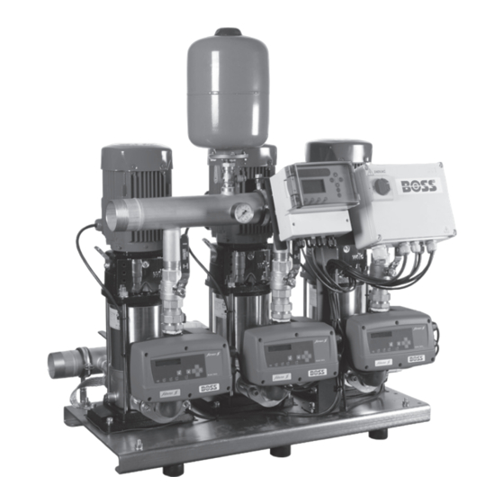
Page 1) General 2) Safety Instructions 2.1 Symbols and Signals 2.2 Risks Incurred by Failure to Comply 2.3 Operator Safety Precautions 2.4 Inspection and assembly 2.5 Modification and Spare Parts 2.6 Unauthorised Operation 3) Transport and Storage 3.1 Storage 3.2 Transport 4) Description and Operation 4.1 Description of the control Device 4.2 Operation Modes... - Page 3 1 General pump or installation. It could also invalidate any The BOSS™ booster set is an automated pressure claims for warranty. In particular, lack of care may boosting systems. Consisting of 1 to 3 vertical lead to problems such as: pumps with in-line water cooled inverters •...
- Page 4 3.2 Transport 4.2.3 Automatic Mode (3 Pump Only) The booster must be transported on a pallet and All controls and settings on a 3 pump set are film wrapped to protect it against moisture and done via the Speedcentre controller (Fig.3) and dust.
- Page 5 4.3.3 Dry Run Protection • The incoming mains connection must comply with local regulations. If air is present in the pumps after a set time the internal dry run protection will operate. Once • As a protection measure, the booster must operated the controller will automatically try to be earthed according to the regulations restart every 30 minutes over a 24 hour period.
-
Page 6: Automatic Mode
8) Figures Fig. 1 - Control box (2 and 3 pump only) Pump MCBs Earth terminals Door interlocked isolator Control terminals: VFC, Low water, Comms Fig. 2 - Electronic Control Drive Manual Mode Inverter On (Green LED) Automatic Mode Alarm (Red LED) Menu Pump Running... - Page 7 Fig. 3 - Speedcentre (3 pump only) Fig. 4 - Pump Schematics...
- Page 8 Fig. 5.1 - Wiring Schematics - 1 Pump System...
- Page 9 Fig. 5.2 - Wiring Schematics - 2 Pump System BOSS_Booster_NON-VFC_230615_[PRINT].pdf 12 23/06/2015 10:52:19 Wiring Diagrams...
- Page 10 Fig. 5.3 - Wiring Schematics - 3 Pump System...
- Page 11 Table 1 - Settings Menu (Hold down menu button to access) MENU SETTINGS FACTORY UNIT Language Language select English I max Set the maximum current rating of the pumps Amps Rotation Sense Change the rotation of the motors Clockwise Min Speed Minimum running speed of the motor Dry Run Prot Turn on or off the dry running protection...
-
Page 12: Error Code
Table 3 - Drive Fault Codes & Troubleshooting ERROR CODE BOOSTER BEHAVIOUR TROUBLESHOOT Check the hydraulic supply. The controller starts the pump every 30 minutes over 24 hours. If dry If a set point pressure higher than the E011 DRY RUN running remains, it switches off the pressure the pump can deliver is pro- pump. - Page 13 Table 4 - Booster Troubleshooting SYMPTOM CAUSES TROUBLESHOOT Suction piping obstructed or valve Check valve opening and clean the piping on suction manifold closed if necessary The pump “fault” indicator on the control Thermal relay tripped box must be lit. Check the setting of the current Switch it again.
- Page 14 10 Spare Parts BOSS Booster Art. No. Spare part Art. No. Part Description Pumps • • • 80460804 HELIX V406-1/16/E/S/400-50-RAL3000 • • • 80460815 HELIX V408-1/16/E/S/400-50-RAL3000 • • • 80460826 HELIX V605-1/16/E/S/400-50-RAL3000 • • • 80460837 HELIX V608-1/16/E/S/400-50-RAL3000 • • •...
-
Page 15: Ec Declaration Of Conformity
EN61000-6-3:2007 +A1:2011 EN61000-6-2:2005 If the above mentioned series are technically modified without our approval, this declaration shall no longer be applicable Authorized representative for the completion of the technical documentation: WILO UK Centrum 100 Second Avenue Burton-Upon-Trent Lee Tebbatt DE14 2WJ...
Need help?
Do you have a question about the BOSS 1-3HELIX V Series and is the answer not in the manual?
Questions and answers