Table of Contents
Advertisement
Quick Links
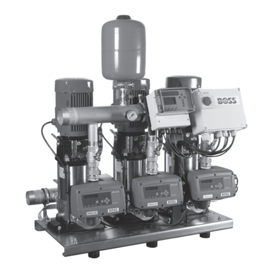
BOSS™ 1-3HELIX V....
EN
Installation and operating instructions
80460601
80460612
80460623
80460634
80460645
80460656
80460667
80460678
80460689
80460708
80460719
80460730
80460741
80460752
80460763
80460774
80460785
80460796
BOSS 1HELIX V406
BOSS 1HELIX V408
BOSS 1HELIX V605
BOSS 1HELIX V608
BOSS 1HELIX V1004
BOSS 1HELIX V1006
BOSS 2HELIX V406
BOSS 2HELIX V408
BOSS 2HELIX V605
BOSS 2HELIX V608
BOSS 2HELIX V1004
BOSS 2HELIX V1006
BOSS 3HELIX V406
BOSS 3HELIX V408
BOSS 3HELIX V605
BOSS 3HELIX V608
BOSS 3HELIX V1004
BOSS 3HELX V1006
Advertisement
Table of Contents

Related Manuals for Wilo BOSS 3HELIX V608


Summarization of Contents
General and Safety
Safety Information and Precautions
Covers safety symbols, risks, operator precautions, inspection, modification, and unauthorized operation.
Transport and Storage
Storage Guidelines
Instructions for storing booster sets in a dry environment between -5°C to +55°C.
Transport Guidelines
Procedures for transporting booster sets on pallets with appropriate lifting equipment.
Description and Operation
Control Device and Operation Modes
Explains the Electronic Control, operation modes (auto/manual) for 1, 2, 3 pump systems, and Speedcentre.
Operating Features
Details fault contacts, low water protection, dry run protection, and master/slave functions.
Installation
Installation Location and Connections
Covers location requirements, hydraulic connections, and electrical connections.
Commissioning and Maintenance
Commissioning Procedures
Recommendations for system commissioning by customer service, including pre-operation checks.
Maintenance Requirements
Details maintenance tasks, including checking diaphragm pressure vessel gas pressure every 6 months.
Figures and Schematics
Control Box and Drive Interface
Illustrations of the control box components and the Electronic Control drive interface.
Speedcentre and Pump Schematics
Diagrams of the Speedcentre controller and the hydraulic layout of pump systems.
Wiring Schematics
Detailed wiring diagrams for 1, 2, and 3 pump systems.
Settings and Troubleshooting
Drive and Speedcentre Settings
Configuration menus for drive and Speedcentre settings, including pressure, speed, and timer.
Troubleshooting Faults and Symptoms
Guides on resolving error codes, common faults, and operational symptoms with causes and solutions.
Booster Specifications and Spares
Maximum Current Ratings
Table detailing maximum current (I max) for different BOSS booster models and pump configurations.
Spare Parts List
Comprehensive list of available spare parts with article numbers and model compatibility.
Need help?
Do you have a question about the BOSS 3HELIX V608 and is the answer not in the manual?
Questions and answers