
Related Manuals for Kistler 4065 Series


Summarization of Contents
Important Information
Protection and Standards
Compliance with CE and directives like ISO 9001, ROHS, ATEX.
Disposal Instructions
Guidance on proper disposal of electronic devices to avoid environmental harm.
Software Updates
Importance of installing software upgrades and liability for outdated software.
Preface
Technical Data and Documentation
Information on where to find technical data sheets for the sensors.
Principle of Operation
Explanation of how the piezoresistive sensor element works and different technologies used.
Media Compatibility
Information on compatible media for DCE and media-separated sensors.
Cooling Requirements
Specifications for coolant temperature, flow rate, pressure, and composition for sensor cooling.
Water Cooling Precautions
Safety guidelines for operating and maintaining the water cooling system for sensors.
Operation
Operation in Non-Hazardous Areas
Guidelines for using sensors without Ex-certification in safe environments.
Hazardous Area Operation Instructions
Rules for using Ex-certified sensors in Zone 2, including installation and modification restrictions.
Sensor Execution Types for Hazardous Areas
Specifies sensor types (4011AE, 4017AE, 4067EE) certified for hazardous area use.
Product Marking for Hazardous Areas
Details on ATEX and IECEx markings for Ex-certified sensors.
Zone 2 Sensor Installation (Ex-ec)
Guidance and conditions for installing Ex-ec certified sensors in Zone 2.
Installation of Piezoresistive Sensor
General Installation Information
Importance of careful installation for accuracy, bore machining, and torque specifications.
Direct Installation
Procedure for direct sensor installation, including thread lubrication and diaphragm protection.
Installation with Sleeve
Method for installing sensors using a mounting sleeve for sealing, particularly in galleries.
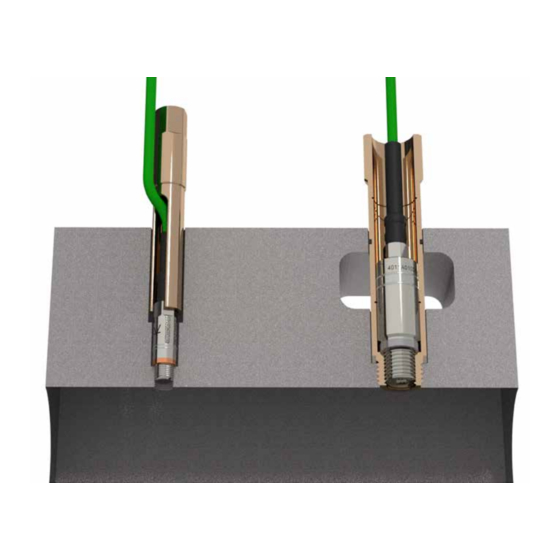
Installation Examples
Visual examples of different sensor installation methods: sleeve, direct, and pipe mounting.
Mounting Bore Machining
Requirements for machining the sensor bore, ensuring concentricity and a flat sealing surface.
Mounting Water Hose on Cooling Pipe
Procedure for fitting the FPM hose onto the sensor's cooling pipe using heat expansion.
Water Cooled Sensor Heat Screen
Maintenance of the protector screen for water-cooled sensors in exhaust applications.
Pre-Installation Checks
Checks for water leakage, cable condition, seal ring integrity, and mounting bore quality.
Installing Sensor into Bore
Steps for feeding the cable, fitting the mounting key, and lubricating threads before installation.
Setting Up Measuring Chain
Analog Compensated Sensors Setup
Procedure for parameterizing amplifiers for analog compensated sensors using calibration data.
Analog Sensors with V200S Extension
Connecting sensors with integrated TEDS and potential manual parameterization needs.
Digital Compensated Sensors Setup
Connecting digital sensors with TEDS; no parameterization needed for compatible amplifiers.
Zero-Point Correction
Zero-Point Correction (Without Cooling)
Steps for zero-point correction for sensors without cooling adapters, involving engine warm-up and barometric adjustment.
Zero-Point Correction (With Cooling)
Procedure for zero-point adjustment with cooled adapters during steady state measurements.
Dismounting and Maintenance
Dismounting Procedure
Step-by-step instructions for safely removing the sensor from the mounting bore.
Maintenance and Inspection
Guidelines for visual inspection, cleaning, and handling of sensors to maintain accuracy.
Need help?
Do you have a question about the 4065 Series and is the answer not in the manual?
Questions and answers