Table of Contents
Advertisement
Quick Links
Advertisement
Table of Contents

Related Manuals for Kistler 4520A Series


Summary of Contents for Kistler 4520A Series
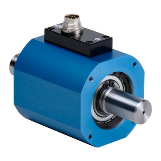
- Page 1 Instruction Manual Basic Line Torque Sensor Type 4520A... ä 4520A_002-515e-02.22...
- Page 2 NC joining system, as needed. The specifications in this manual can change at any time without prior notification. Kistler reserves the right to im- prove and to change the product for the purpose of tech- nical progress without the obligation to inform persons and organizations as the result of such changes.
-
Page 3: Table Of Contents
Basic Line Torque Sensor, Type 4520A... Content Introduction ........................... 3 Important Information ........................4 Disposal Instructions for Electrical and Electronic Equipment ..........4 Application and Key Features ......................5 Description of the Measuring System .................... 6 Mechanical Design ....................... 6 Electrical Block Diagram ....................... -
Page 4: Introduction
It will help you with the installation, maintenance, and use of this product. To the extent permitted by law Kistler does not accept any liability if this instruction manual is not followed or prod- ucts other than those listed under Accessories are used. -
Page 5: Important Information
Do not discard old electronic instruments in municipal trash. For disposal at end of life, please return this product to an authorized local electronic waste disposal service or contact the nearest Kistler Instrument sales office for return instructions. Page 4... -
Page 6: Application And Key Features
Application and Key Features Application and Key Features Measuring ranges from 1 ... 1 000 N·m Speed up to 10 000 min Torque meter with strain gages measuring system Wear-resistant transmission of the measuring signal, inte- grated amplifier ... -
Page 7: Description Of The Measuring System
Basic Line Torque Sensor, Type 4520A... Description of the Measuring System Mechanical Design Basic Line torque sensors Type 4520A… consist of a base body which contains the measuring shaft. On the mea- suring shaft there is a torsional section with strain gages and electronics with signal amplifier and A/D transformer. -
Page 8: Electrical Block Diagram
Description of the Measuring System Electrical Block Diagram Fig. 3: Electrical block diagram 4520A_002-515e-02.22 Page 7... -
Page 9: Examples Of Application
Basic Line Torque Sensor, Type 4520A... 4.2.1 Examples of Application Strict use of electrical isolation for feed and measuring sig- nal. Feed Feed device Control Feed Evaluation output electronic Shield Fig. 4: Separate speed and measuring supply Shared access measuring supply for feed and measuring supply. -
Page 10: Electrical Configuration Of Speed Measurement
Description of the Measuring System 4.3 Electrical Configuration of Speed Measurement Speed measurement is effected photo-electrically by evaluating the light, which shines through a grid wheel. A gallium-arsenide light diode serves as transmitter emitting in the near infrared. In a phototransistor the light is converted into an electric signal and after a "open collector"... -
Page 11: Electrical Connections Of The Sensor
Basic Line Torque Sensor, Type 4520A... Electrical Connections of the Sensor Shielded lead Lead connector To power supply unit and display Torque sensor Type 4520A… Fig. 8: Electrical connections Shielded lead of 0,14 mm² nominal cross section Page 10 4520A_002-515e-02.22... -
Page 12: Plug Connection
Electrical Connections of the Sensor Plug Connection Pin Allocation of Built-in 12 pin Connector Function Descripption Power Supply 18 ... 26 VDC, power consumption <2 W Reference for U and angle signals Shield In sensor; connected to case Torque output ±10 VDC at M at >2 kΩ... -
Page 13: Instruction For Electrical Installation
Basic Line Torque Sensor, Type 4520A... 5.2 Instruction for Electrical Installation Plug Connector housing Ω Ω Load machine with inventor or alike device Ω Type 4520A… Remove anodic coating if neccessary Stator min 16 Stator support min. 18 VDC ripple max. -
Page 14: Cable And Connection Torque Sensor Type 4520A
Electrical Connections of the Sensor Cable and Connection Torque Sensor Type 4520A... Please see cable data sheet 000-615 Material No. 18008943 / 18008944 (free end) Cable definition violet yellow pink grey blue green black white grey/pink brown ---- Type 5867… 4520A_002-515e-02.22 Page 13... - Page 15 Basic Line Torque Sensor, Type 4520A... Type 5877… Page 14 4520A_002-515e-02.22...
-
Page 16: Mechanical Installation Of The Torque Sensor
Electrical Connections of the Sensor 5.4 Mechanical Installation of the Torque Sensor There are different methods of installing the torque sensor, depending on the application. Since very high lateral forces and bending moments may occur even at small axial displacement, the torque sensor must always be mounted with couplings. -
Page 17: Possible Installation Type 4520A
Basic Line Torque Sensor, Type 4520A... 5.5 Possible Installation Type 4520A... Torque sensor between drive and brake Drive (specimen) Half couplings Brake Type 2302A... Twist protection Torque sensor (should not apply heavy tension-forces on the torque sensor) Fig. 10: Together with the half couplings the torque sensor forms a full coupling Couplings compensate for axial-radial and angular mis- alignment. -
Page 18: Mechanical Application And Mechanical Installation Of The Torque Sensor Type 4520A
Mechanical Application and Mechanical Installation of the Torque Sensor Type 4520A... 6. Mechanical Application and Mechanical Installation of the Torque Sensor Type 4520A... Frictional Torque Control in Production Engine Angle support Torsion proof miniature coupling double-flexible with clamping hub Type 2303A... Basic Line Torque Sensor rotating with contactfree signal transmission... -
Page 19: Torque Measuring Shaft Version Ra
Basic Line Torque Sensor, Type 4520A... Torque Measuring Shaft Version RA For the electric connection of measuring shaft and supply- and evaluation unit we recommend to use the shielded signal lead, Type KSM072030-5 (Mat. No.: 18008943) with low capacity. As supply and evaluation unit we suggest the Control Monitor CoMo Torque Type 4700B... -
Page 20: Supply And Evaluation
Mechanical Application and Mechanical Installation of the Torque Sensor Type 4520A... 6.3 Supply and Evaluation sensor only operated using filtered +18 … 26 VDC voltage. Recommended supply voltage: Type 4700B... +18 ... 26 V Type 4520A… (Data sheet 000-944) (Data sheet 000-765) Terminal box for Type 4520A…... -
Page 21: Static Calibration
Basic Line Torque Sensor, Type 4520A... Static Calibration This procedure requires the use of a calibration device with a lever arm and weights for producing specific values of torque. The calibration procedure is as follows Apply the rated value of torque to the torque meter and then remove it again ... -
Page 22: Calculation Example For Lever Arm Length
Static Calibration Calculation Example for Lever Arm Length , whereby ⋅ = Torque = Length of lever arm required = Mass required = 9.80665 m/s² (= standard gravity – varies with location) Fig. 14: Calculation of lever arm length Example: m = 1 kg Mt = 10 N·m... -
Page 23: Maintenance
Basic Line Torque Sensor, Type 4520A... Maintenance Sensors of the Type 4520A… are almost maintenance- free. Durability of bearings in rated temperature range is ap- prox. 20 000 hours. Durability of bearings in working temperature range is ap- prox. -
Page 24: Repairs
Repairs Repairs Fault Cause Remedy Bearing defect due to a) torsional or flexural vibration Shaft stiff to turn b) high axial or radial loads Return to factory c) worn bearings d) bent shaft The zero reading can Torsional vibration Zero shift less than 2 % be readjusted at the Torsional shock display. -
Page 25: Accessories And Ordering Key
Basic Line Torque Sensor, Type 4520A... 10. Accessories and Ordering Key Page 24 4520A_002-515e-02.22... -
Page 26: Index
Index 11. Index Accessories and Ordering Key ......24 Important Information ........4 Application/Key Feautures ........ 5 Installing the Signal Lead ....... 11 Applikationsbeispiele ........8 Instruction for Electrical Installation ....12 Introduction ............. 3 Calculation Example for Lever Arm Length ..21 Construction Calibration Device .....
Need help?
Do you have a question about the 4520A Series and is the answer not in the manual?
Questions and answers