Table of Contents
Advertisement
Quick Links
S.I. Instruments
256 South Rd. Hilton
South Australia 5033
Ph (08) 8352 5511
info@si-instruments.com
www.si-instruments.com
Instruction
Manual
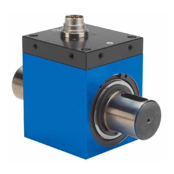
Mini-Smart Torque
Sensor
Type 4502A
Version Q
(with standard square
connections)
Version H
(with standard hexagon
connections)
Version QA/HA
(with rotating angle
measuring system)
Version RA
(with round shaft and
rotation angle
measurement)
4502A_002-407e-03.08
Advertisement
Table of Contents

Related Manuals for Kistler 4502A Series


Summary of Contents for Kistler 4502A Series
- Page 1 S.I. Instruments 256 South Rd. Hilton South Australia 5033 Ph (08) 8352 5511 info@si-instruments.com www.si-instruments.com Instruction Manual Mini-Smart Torque Sensor Type 4502A Version Q (with standard square connections) Version H (with standard hexagon connections) Version QA/HA (with rotating angle measuring system) Version RA (with round shaft and rotation angle...
- Page 3 Information in this document is subject to change without notice. Kistler reserves the right to change or improve its products and make changes in the content without obligation to notify any person or organization of such changes or improvements.
-
Page 4: Table Of Contents
Mini-Smart Torque Sensor Type 4502A Content Introduction..........................3 Important Information .......................4 Disposal Instructions for Electrical and Electronic Equipment..........4 Application and Key Features.....................5 Description of the Measuring System..................6 Mechanical Design ......................6 Electrical Block Diagram....................7 4.2.1 Examples of Application ..................8 Rotation Angle Measuring System (Version QA/HA and RA only) ........9 Adjustment for Angle-Pulse Output (Version QA/HA and RA only)........ -
Page 5: Introduction
Please take the time to thoroughly read this instruction manual. It will help you with the installation, maintenance, and use of this product. Kistler offers a wide range of products for use in measuring technology: § Piezoelectric sensors for measuring force, torque, strain,... -
Page 6: Important Information
Do not discard old electronic instruments in municipal trash. For disposal at end of life, please return this product to an authorized local electronic waste disposal service or contact the nearest Kistler Instrument sales office for return instructions. Page 4... -
Page 7: Application And Key Features
Application and Key Features Application and Key Features § Torque meter with strain gages measuring system § Wear-resistant transmission of the measuring signal, integrated amplifier § Measurement of constant and variable torques § Torque measurement on the rotating shaft § Integrated system for rotation angle measurement (only version QA/HA) §... -
Page 8: Description Of The Measuring System
Mini-Smart Torque Sensor Type 4502A Description of the Measuring System Mechanical Design Torque Sensors type MS consist of a base body which contains the measuring shaft. The shaft ends are performed as standard square connections or standard hexagon ends. On the measuring shaft there is a torsion distance with strain gauges and electronics with signal amplifier and A/D transformer. -
Page 9: Electrical Block Diagram
Description of the Measuring System Electrical Block Diagram Feed and inspection input of electronic measuring equipment, electrically isolated feed internal power supply 11...26 VDC fiber optic rotary joint control Opto- Rotor Logic and 5...30 VDC coupler electronics modulator control frequency/ strain gages potential measuring... -
Page 10: Examples Of Application
Mini-Smart Torque Sensor Type 4502A 4.2.1 Examples of Application Exactly use of electrical isolation for feed and measuring signal. Feed device feed control Evaluation feed electronic output shield Fig. 4: Separate speed and measuring supply Shared access measuring supply for feed and measuring supply. -
Page 11: Rotation Angle Measuring System (Version Qa/Ha And Ra Only)
Description of the Measuring System 4.3 Rotation Angle Measuring System (Version QA/HA and RA only) +5 V Fig. 6: Diagram showing the design of the rotation angle measuring system 1. Rotating shaft 2. Pulse disk 3. Forked light barrier with LED and photo diode 4. -
Page 12: Adjustment For Angle-Pulse Output (Version Qa/Ha And Ra Only)
Mini-Smart Torque Sensor Type 4502A 4.4 Adjustment for Angle-Pulse Output (Version QA/HA and RA only) Output Pin B Output Pin G with drive on square socket or hexagon end sense of rotation cw View A 1: sense of rotation drive side (version QA) View A 2: sense of... -
Page 13: Electrical Connections
Electrical Connections Electrical Connections Shielded lead Lead connector To power supply unit and display Torque sensor (all versions) Fig. 8: Electrical connections § Shielded lead of 0,14 mm² nominal cross section 4502A_002-407e-03.08 Page 11... -
Page 14: Plug Connection (Tuchel, 12 Pin)
Mini-Smart Torque Sensor Type 4502A Plug Connection (Tuchel, 12 pin) Function Top view built-in plug GND electric calibration input signal Angle 1, speed Measuring signal U ±5 VDC GND measuring signal U ±5 VDC GND supply voltage U , angle, speed Supply voltage U +11 V ... -
Page 15: Instruction For Electrical Installation
Electrical Connections 5.2 Instruction for Electrical Installation plug connector housing load machine with inventor or alike device 4502A anodic coating contingent stator to delete min 16 stator support unit min 16 V DC ripple max. 100 mV 4502A length max. 50 m 0,25 Fig. -
Page 16: Connecting Cable
Mini-Smart Torque Sensor Type 4502A 5.3 Connecting Cable 5.3.1 Cable Diagram with Plugs on Both Sides wh= white re= red bl= black blu= blue pi= pink gr= green gr= grey vi= violett Fig. 10: Cable diagram with plugs on both sides 5.3.2 Cable Diagram, Plug (Sensor), Open Ends, Article-No.: 12497 Fig. -
Page 17: Mechanical Application
Mechanical Application Mechanical Application Versions Q, QA, H and HA § Torque meters of version Q and QA have square connections for plug-in tools acc. to DIN 3121 § Torque meters of version H and HA have hexagon connections acc. to DIN 3126, form E/F §... -
Page 18: Torque Measuring Shaft Version Ra
Mini-Smart Torque Sensor Type 4502A Torque Measuring Shaft Version RA For the electric connection of measuring shaft and supply- and evaluation unit we recommend to use the shielded signal lead, art. no. 7203 with low capacity. Version VA 3600 is recommended as supply and evaluation unit. The signal lead should not exceed a length of 30 meters. -
Page 19: Possible Installation Of Version Ra
Mechanical Application 6.3 Possible Installation of Version RA firm stator (4502A version RA) specimen with full coupling on both sides Full coupling Full coupling fixed bearing fixed bearing on both sides specimen retaining angle drive brake with fixed bearing Fig. 13: Application example version R Couplings compensate axial-radial and angular misalign- ment. -
Page 20: Supply Circuit And Evaluation
Mini-Smart Torque Sensor Type 4502A 6.4 Supply Circuit and Evaluation VA 3600 4502A +16 V ... 30 VDC Data sheet 4160 Version RA Terminal box for 4502A version RA Torque output ±5 VDC Panel meter Torque output 1 5 V,TTL Quadrature counter Torque output 2 5 V,TTL... -
Page 21: Static Calibration
Static Calibration Static Calibration This procedure requires the use of a calibration device with a lever arm and weights for producing specific values of torque. The calibration procedure is as follows: § Apply the rated value of torque to the torque meter and then remove it again §... -
Page 22: Calculation Example For Lever Arm Length
Mini-Smart Torque Sensor Type 4502A Calculation Example for Lever Arm Length , whereby × Torque Length of lever arm required Mass required 9.80665 m/s² (= standard gravity varies with location) Fig. 14: Calculation of lever arm length Example: m = 1 kg 10 N·m 10 N·m s... -
Page 23: Maintenance
Maintenance Maintenance § Sensors of the MS series are almost maintenance-free § Durability of bearings in rated temperature range is approx. 20 000 hours § Durability of bearings in working temperature range is approx. 10 000 hours § Renewal of bearings can only be effected at works §... -
Page 24: Repairs
Mini-Smart Torque Sensor Type 4502A Repairs !#*&) #*(% "%’%$+ Shaft stiff to turn Bearing defect due to: Return to factory a) Torsional or flexural vibration b) High axial or radial loads c) Worn bearings d) Bent shaft Zero shift less than 2% Torsional vibration The zero reading can Torsional shock...
Need help?
Do you have a question about the 4502A Series and is the answer not in the manual?
Questions and answers