Table of Contents
Advertisement
EN
2 1 . 1 0 - 5 2 9 9 7 8 6 _ 0 2
T r a n s l a t i o n f r o m o r i g i n a l
S G E
2 5 0 - 3 5 0 - 5 0 0 - 7 0 0
I n s t a l l a t i o n m a n u a l
50Hz
Q
OUTDOOR UNITS
C o o l i n g c a p a c i t y 2 , 7 7 ÷ 5 , 8 6 k W
H e a t i n g c a p a c i t y 2 , 9 3 ÷ 6 , 0 0 k W
w w w . a e r m e c . c o m
Advertisement
Table of Contents

Related Manuals for AERMEC SGE500


Summary of Contents for AERMEC SGE500
- Page 1 2 1 . 1 0 - 5 2 9 9 7 8 6 _ 0 2 T r a n s l a t i o n f r o m o r i g i n a l S G E 2 5 0 - 3 5 0 - 5 0 0 - 7 0 0 I n s t a l l a t i o n m a n u a l 50Hz...
- Page 3 Dear customer, Thank you for choosing an AERMEC product. It is the fruit of many years of experience and special design studies and has been made of the highest grade materials and with cutting edge technology. In addition, all our products bear the CE mark indicating that they meet the requirements of the European Machine Directive regarding safety.
- Page 4 Frequenza 50 Hz Frequency 50 Hz Fréquence 50 Hz Frequenz 50 Hz Frecuencia 50 Hz 50Hz Gas refrigerante R32 refrigerant Réfrigérant R32 R32-Kältemittel Refrigerante R32 Raffreddamento e Cooling and Refroidissement et Kühlung und Frío y calor riscaldamento heating chauffage Heizung Wi-Fi Wi-Fi Wi-Fi...
-
Page 5: Table Of Contents
INDEX SAFETY STANDARDS R32 GAS ......................................6 WARNINGS ..............................................8 RECEIVING THE PRODUCT .......................................12 TECHNICAL DATA ..........................................13 GENERAL DATA .............................................14 UNIT TYPE ...............................................15 FEATURES ..............................................15 OPERATING LIMITS..........................................15 PARTS OF THE UNIT ..........................................15 SIZES AND WEIGHTS ..........................................16 TECHNICAL DIMENSIONS ........................................17 MINIMUM TECHNICAL CLEARANCES ..................................19 NOTES FOR INSTALLATION OF UNIT ....................................20 OUTDOOR UNIT INSTALLATION ....................................22 CONDENSATE DISCHARGE ......................................25... -
Page 6: Safety Standards R32 Gas
SAFETY STANDARDS - R32 GAS WARNINGS FOR MAINTENANCE OR REPAIR THESE PROCEDURES MAY ONLY BE FOLLOWED BY SPECIALISED TECHNICIANS OR QUALIFIED GAS R32 GENERAL WARNINGS PERSONNEL. Please follow the steps below: WARNING 1. Turn off the unit and disconnect it from the electrical Please read this manual carefully before power supply. - Page 7 WARNING: Do not use means to accelerate the defrosting process or to clean, other than those recommended by the manufacture. Should repair be necessary, contact your nearest authorized Service Centre. Any repairs carried out by unqualified personnel may be dangerous. The appliance shall be stored in a room without continuously operating ignition sources.
-
Page 8: Warnings
cables, plug or power socket overheating, which WARNINGS could present a fire risk. • Make sure all the electric cables and wires are well arranged and closed in the unit's electric box to WARNING: Strictly observe the warnings below. Failure avoid any damage due to corrosion, overheating, to observe them, could result in injuries to people or fires or electric shock. - Page 9 earth cable of the telephone. Incorrect earthling/ • If the units are installed in a location exposed to grounding could cause electric shocks. electromagnetic interference, shielded twisted • Keep the power cables, plug and socket clean. pair cables must be used for the communication Remove any dust or dirt that may accumulate connections between the units.
- Page 10 which stores the settings in the memory. PRECAUTIONS FOR USE • If there is a power cut, when the power is restored the air conditioner will restart with the settings • Ensure the equipment is not used by children or previously stored in the memory.
- Page 11 2. Error code, explaining what happened before and after the error warning. DISCLAIMER AERMEC DOES NOT ASSUME ANY RESPONSIBILITY FOR DAMAGES TO THE UNIT OR WARRANTY LOSS IN CASE: 1. The unit is used improperly. 2. Attempts to modify, alter or repair the unit were made without following the previously mentioned instructions.
-
Page 12: Receiving The Product
Placed on the packaging, displays the data identifying the The technical plate, located inside the unit, displays the product. product's technical and identifying data. AERMEC S.p.A. VIA ROMA 996 AERMEC S.p.A. VIA ROMA 966 BEVILACQUA (VR) ITALY BEVILACQUA (VR) ITALY... -
Page 13: Technical Data
TECHNICAL DATA Indoor unit SGE250W SGE350W SGE500W SGE700W Outdoor unit SGE250 SGE350 SGE500 SGE700 Nominal cooling performances Cooling capacity (1) 2,77 3,46 5,27 5,86 Cooling input power (1) 0,77 1,06 1,55 1,81 EER (2) 3,60 3,25 3,40 3,24 Moisture removed... -
Page 14: General Data
675kgCO eq Equivalent CO 0,37 0,37 0,73 0,96 (1) Sound pressure measured in semi anechoic chamber at a distance of 1 m from the source. GENERAL DATA Indoor unit SGE250W SGE350W SGE500W SGE700W Outdoor unit SGE250 SGE350 SGE500 SGE700 Electric data... -
Page 15: Unit Type
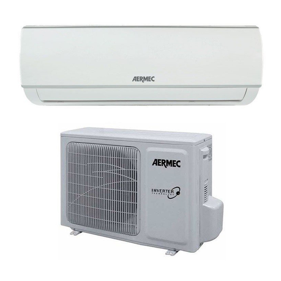
UNIT TYPE PARTS OF THE UNIT Split air conditioners, reversible air/air heat pumps with Outdoor unit DC inverter technology. The monosplit air conditioners of the SGE range are combined with SGE_W (Wall) indoor units for wall installation. The outdoor unit boasts an inverter rotary compressor, inverter fan and an electronic valve. -
Page 16: Sizes And Weights
SIZES AND WEIGHTS Carton Box Example Outdoor unit SGE250 SGE350 SGE500 SGE700 Net weight Weight for transport... -
Page 17: Technical Dimensions
TECHNICAL DIMENSIONS SGE250 - SGE350 (mm) SGE500 (mm) - Page 18 SGE700 (mm)
-
Page 19: Minimum Technical Clearances
MINIMUM TECHNICAL CLEARANCES • The installation site must guarantee drainage of CHOOSING THE INSTALLATION AREA FOR THE rainwater and water produced during the defrosting OUTDOOR UNIT cycle. • Always ensure adequate condensate drainage is • To guarantee the unit operates correctly, the choice installed. -
Page 20: Notes For Installation Of Unit
INSTALLATION NOTES FOR INSTALLATION OF UNIT forehand; this should only be carried out by “Person- nel with specific technical skills”. • To ensure good drainage, the condensate discharge pipes must be correctly installed, following the instal- WARNINGS CONCERNING INSTALLATION lation instructions. Adopt the most suitable measures to avoid heat dispersion and the consequent forma- The unit and its accessories must only be installed and tion of condensate. - Page 21 INSTALLATION • In salty coastal areas, or in areas near sulphurous hot springs, contact the retailer before installation to en- sure the unit can be safely used. • Do not install in laundries. • Do not install in places where there is a high percent- age of humidity in the air.
-
Page 22: Outdoor Unit Installation
OUTDOOR UNIT INSTALLATION STEP 1 STEP 3 Position the unit on the relative supports. Fix the support in the point where the outdoor unit Fasten the unit feet with screws and bolts. will be placed (the installation must be carried out following all instructions previously given in this document). - Page 23 5. Remove the nuts from the expansion bolts and CONNECTIONS/CONTROL BOARD COVER place the outdoor unit on the bolts. 6. Insert the washer onto each expansion bolt then replace the nuts. 7. Using a wrench, tighten each nut until it is snug. SCREW If you install the unit on the wall: 1.
- Page 24 Tighten the nut with a torque wrench, referring to the following section: TIGHTENING TORQUE FOR FLARED CONNECTIONS Tightening Tube diameter Tube thickness torque mm (inches) (mm) (Nm) 6,35 (1/4”) ≥ 0,8 15~20 9,52 (3/8”) ≥ 0,8 30~40 12,7 (1/2”) ≥ 0,8 45~55 15,9 (5/8”) ≥...
-
Page 25: Condensate Discharge
CONDENSATE DISCHARGE The outdoor unit when working in heat pump 1. Mount the rubber gasket on the end of the produces condensate water. To prevent condensate condensate drain connection that will connect to dripping on underlying objects or creating problems the outdoor unit. -
Page 26: Cooling Connections
• Try to avoid bending the pipes. If you must bend them, the bend radius should be greater than 100mm. SELECTION OF THE REFRIGERANT CONNECTION LINES Indoor units SGE250W SGE350W SGE500W SGE700W Outdoor units SGE250 SGE350... - Page 27 FITTING THE CONNECTION PIPE Outdoor unit Indoor unit GAS line LIQUID line Condensate discharge Siphon OUTDOOR UNIT BELOW AND INDOOR UNIT OUTDOOR UNIT ABOVE AND INDOOR UNIT ABOVE BELOW In this case it is necessary to install a siphon In this case, provision must be made on the (F) every 10 metres of height difference on suction piping (C) for siphons (F) every 3 the suction piping (C) in order to block the...
-
Page 28: Creating The Refrigerant Lines
CREATING THE REFRIGERANT LINES To prepare the copper pipes, proceed as follows: External Pipe Tightening 1. Measure the inner and outer pipe precisely. Pipe thickness Diameter Torque 2. Use a pipe which is slightly longer than the inch (mm) measurement taken. 3. - Page 29 Fig. A Fig. B Fig. C Fig. D Fig. E Fig. F...
-
Page 30: Notes For The Construction Of Refrigerant Lines
NOTES FOR THE CONSTRUCTION OF REFRIGERANT LINES Gas pipe • When connecting the indoor unit to the connection Electrical cables pipe, do not force the couplings on the indoor unit, as this could cause cracks in the capillary pipes and other pipes on the indoor unit, causing them to leak. -
Page 31: Creating A Vacuum And Topping Up The Refrigerant Gas Charge
CREATING A VACUUM AND TOPPING UP THE REFRIGERANT GAS CHARGE 1. CREATING A VACUUM AND TOPPING UP THE REFRIGERANT GAS CHARGE The fitter must be equipped with: • A vacuum pump for chiller systems, ideally a two-stage pump, equipped with a non-return valve in the event of a power cut or if the pump is switched off. - Page 32 HIGH CHECKING THE CONNECTION HOSES AND LEVEL OF VACUUM CREATED BY THE PUMP; Switch on the vacuum pump. To connect the two hoses and thereby connect the LP side to the vacuum pump: • Open the blue valve marked “LOW” on the pressure gauge unit. •...
- Page 33 When the vacuum pump shows a sufficient level of vacuum, wait a few minutes and then proceed with the following operations: • Close the yellow valve marked “VAC”. • Switch off the vacuum pump. • Check that the vacuum gauge does not show a drop in the vacuum level compared with when the pump was operating.
-
Page 34: Leak Detector
LEAK DETECTOR 1. With leak detector: Check whether there are leaks with the leak detector. 2. With soapy water: If the leak detector is not available, use soapy water for detecting the leaks. Apply soapy water on the suspected position and keep the soapy water for more than 3 minutes. -
Page 35: Electrical Connections
pipe, the compressor or moving parts such as the ELECTRICAL CONNECTIONS fans. • Do not modify the circuits inside the air conditioner. The manufacturer cannot be held responsible for • Before carrying out any work, switch off the power any damage or malfunction due to incorrect line supply to the air conditioner. -
Page 36: Checks On Electrical Devices
CHECKS ON ELECTRICAL DEVICES NOTE: • Circuit Breaker and Power Cord Specifications are selected according to the Rated Power Input (Rated Current Input) of the Unit. Rated Power Input (Rated Electrical component repair and maintenance Current Input) is “Maximum” Power Input (“Maximum” procedures must include initial safety checks and Current Input) of the Unit according to EN 60335-1 component inspection procedures. -
Page 37: Electrical Wiring Between The Indoor And Outdoor Unit
ELECTRICAL WIRING BETWEEN THE INDOOR AND OUTDOOR UNIT SGE250 - SGE350 - SGE500 - SGE700 SGE250W - SGE350W SGE500W - SGE700W OUTDOOR UNIT INDOOR UNIT N(1) N(1) POWER 220-240V~50Hz YEGN TERMINAL TERMINAL BLOCK BLOCK OUTDOOR UNIT SGE250 SGE350 SGE500 SGE700... -
Page 38: Wiring Diagrams
WIRING DIAGRAMS SGE250 - SGE350 - SGE500 NOTES Notes: YELLOW OR BLACK This symbol BLUE OR BLACK BLUE This symbol indicates the element is optional, the actual shape shall be prevail. indicates the element BROWN This symbol indicates the is optional, the actual element exist various locations. - Page 39 SGE700 NOTES Notes: OPTIONAL BLACK BLUE(BLACK) This symbol BLUE This symbol indicates the element is BROWN indicates the element is optional,the actual shape shall be prevail. optional, the actual shape 1(L) 2(N) shall be prevail. CN 3 The D box contains the ground wire of the OPTIONAL OUTDOOR...
-
Page 40: Operating Test
OPERATING TEST Before commissioning the air conditioner, an operating test must be performed. Proceed as follows: Preparing for the test: 1. Check that the network voltage is correct. 2. Do not connect the unit to the power supply before installation is complete. 3. -
Page 41: Checks To Be Carried Out After Installation
CHECKS TO BE CARRIED OUT AFTER INSTALLATION ITEMS TO CHECK POSSIBLE ANOMALY SITUATION Is the unit firmly fixed? The unit could fall, vibrate or generate noise. Has a check been made for refrigerant Poor performance. leaks? Is the thermal insulation sufficient? It could produce condensate and lead to dripping water. -
Page 42: Maintenance
MAINTENANCE GENERAL NOTES CHECK BEFORE STARTING • Check to make sure that the inlet and outlet are not • Disconnect the power supply before cleaning the obstructed by objects on both units, external and unit. internal. • Disconnect the power supply when the air •... -
Page 43: Troubleshooting
TROUBLESHOOTING TROUBLESHOOTING Irregularity Possible reasons The unit doesn't start when the ON/ The unit is fitted with a 3-minute protection system that prevents it from OFF button is pressed becoming overloaded. The unit cannot be restarted within 3 minutes of switch-off. - Page 44 Irregularity Possible reasons Operation is irregular or Interference from cell towers and remote boosters may cause the unit to unpredictable, and/or the unit does malfunction. not respond to the commands In this case, proceed as follows: Disconnect and then reconnect the power supply. Press the ON/OFF button on the remote control to restart operation.
- Page 45 The unit often switches on and Low refrigerant load. Check there are no refrigerant off autonomously. leakages in the system, then reload the refrigerant. (Refer to the relative paragraph in this manual). Gas or incompressible humidity has Drain the system and then reload it entered the system.
-
Page 46: Error Code Table
ERROR CODE TABLE If malfunctioning occurs during system functioning, the units show the relative alarm code which easily permits to the After-Sales Service Area to identify the cause of errors. When the indoor unit encounters a recognized error, the operation lamp will flash in a corresponding series, the timer lamp may turn on or begin flashing, and an error code will be displayed. - Page 47 Operation lamp Timer lamp Display Error information Solution 5 times FLASH Inverter compressor drive error TS34 7 times FLASH Low pressure protection (for some models) TS35 Indoor units mode con ict (match with multi outdoor 6 times FLASH P5/-- unit) For other errors The display board may show a garbled code or a code undefined by the service manual.
- Page 48 FOR SOME MODELS Operation lamp Timer lamp Display Error information Solution 1 time Indoor unit EEPROM parameter error TS19 EH 00 2 times Indoor / outdoor unit communication error TS20 EL 01 3 times Zero-crossing signal detection error (for some models) TS22 EH 02 The indoor fan speed is operating outside of the normal 4 times...
- Page 49 LED FLASH FREQUENCY 0,4 s 1,2 s 0,4 s 0,4 s 1,2 s 0,4 s ..ERROR DISPLAY (FOR SOME OUTDOOR UNITS) There are two LED lights (a red and a green one) welded in outdoor main board. After power ON, LED show different actions when encounter different problems.
- Page 52 SCARICA L’ULTIMA VERSIONE: DOWNLOAD THE LATEST VERSION: TÉLÉCHARGER LA DERNIÈRE VERSION: http://www.aermec.com/qrcode.asp?q=17812 http://www.aermec.com/qrcode.asp?q=17813 http://www.aermec.com/qrcode.asp?q=17814 A E R M E C S . p . A . V i a R o m a , 9 9 6 - 3 7 0 4 0 B e v i l a c q u a ( V R ) - I t a l y T e l .
Need help?
Do you have a question about the SGE500 and is the answer not in the manual?
Questions and answers