Table of Contents
Advertisement
Quick Links
Advertisement
Table of Contents

Related Manuals for AERMEC SC1200


Summary of Contents for AERMEC SC1200
- Page 1 2 1 . 0 3 - 5 3 8 9 9 4 6 _ 0 1 T r a n s l a t i o n f r o m o r i g i n a L S C 1 2 0 0 + S C 1 2 0 0 V U s e a n d i n s t a l l a t i o n m a n u a l 50Hz ■...
- Page 2 Dear customer, Thank you for choosing an AERMEC product. It is the fruit of many years of experience and special design studies and has been made of the highest grade materials and with cutting edge technology. In addition, all our products bear the CE mark indicating that they meet the requirements of the European Machine Directive regarding safety.
-
Page 3: Table Of Contents
MAINTENANCE AFTER USE ..........25 OPERATING LIMITS ............7 ALARMS DISPLAY ............26 TECHNICAL DATA ............8 15.1. ALARM CODES FOR THE UNITS SC1200 ......26 15.2. PANEL ON THE MACHINE ..........27 DESCRIPTION OF COMPONENTS ........9 FUNCTIONS AVAILABLE THROUGH NOTES FOR INSTALLATION OF UNITS ...... -
Page 4: Warnings
WARNINGS cient technical clearance around the unit for maintenance. PURPOSE OF THE UNIT: • When installing the unit, ensure 1.1. WARNINGS FOR THE FITTER that the dimensions and weight of Split-system air conditioners are the unit are visible. Respect the di- designed solely for the purpose •... -
Page 5: Warnings For The User
cables must be protected. • Do not dismantle or repair the unit jects, into the sockets or air vents. • Do not make connections on the while it is in operation. • Do not place objects on the out- power supply cable: use a longer •... -
Page 6: Unit Type
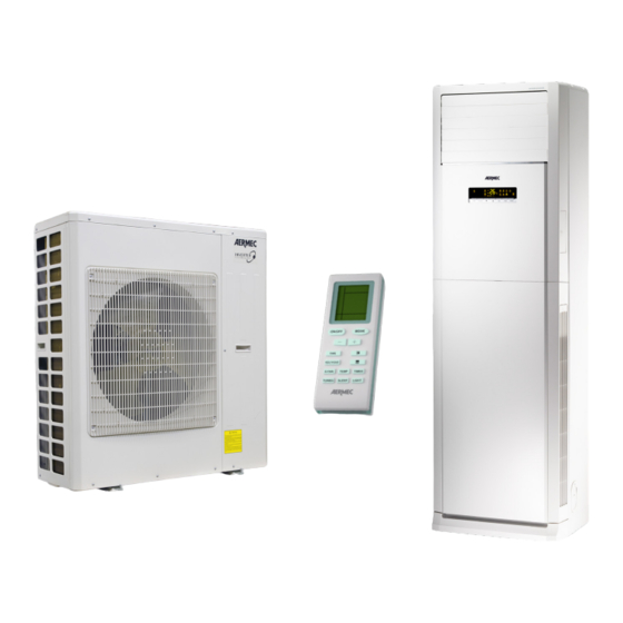
UNIT TYPE Remote control Column type air conditioning units are ideal for all large environments, com- pact and easy to install they are the Indoor unit perfect solution for environments such as shops, restaurants, shopping centres or medical centres. Outdoor unit These units are equipped with a control panel on the machine and are also pro- vided with an infra-red remote control. -
Page 7: Features
• Outdoor unit with connection for unit via a display, and icons also on the condensate discharge OPERATING LIMITS Indoor unit (°C) Outdoor unit (°C) SC1200 Temperature D.B. Temperature W.B. Temperature D.B. Temperature W.B. Nominal Cooling Maximum... -
Page 8: Technical Data
TECHNICAL DATA Indoor units SC1200V Outdoor units SC1200 Cooling capacity Nominal (Min÷Max) 12000 (3000 ÷ 13000) Total input power Nominal (Min÷Max) 4000 (660 ÷ 5400) Current Dehumidifying Volume Energy Efficiency Class SEER Seasonal Efficiency Pdesignc 12,0 Annual Electricity Consumption kWh/annum Heating Capacity Nominal (Min÷Max) -
Page 9: Description Of Components
DESCRIPTION OF COMPONENTS Indoor unit SC1200V Ambient air outlet receiver remote control Air inlet Condensate discharge Electrical wirings (serial + power supply) External air inlet R410A Chiller connections (Liquid / Gas) External air outlet Outdoor unit SC1200 Power Supply 380-415V -3N~50Hz... -
Page 10: Notes For Installation Of Units
INSTALLATION OF UNIT NOTES FOR INSTALLATION OF UNIT 8.1. WARNINGS CONCERNING winds, typhoons and earthquakes. the retailer before installation to en- INSTALLATION Incorrect installation could cause sure the unit can be safely used. the device to fall, and lead to ac- •... -
Page 11: Outdoor Unit Installation
OUTDOOR UNIT INSTALLATION 9.1. OUTDOOR UNIT DIMENSIONS SC1200 (mm) 1107 1107 1018 Weight (kg) 1018 9.2. -
Page 12: Dimensions Of The Indoor Unit
drainage is installed. The condensate drain connection supplied with the unit (external diameter of the connection = 15.8mm) must be installed below the base of the outdoor unit and connected to a pipe of a suitable diameter. • The site of installation must be posi- tioned so that the discharge air outlet is not exposed to strong winds and the air discharged must be free to disperse... -
Page 13: Choosing The Installation Area For The Indoor Unit
9.6. CHOOSING THE INSTALLATION AREA densate drainage and easy connection to the electrical appliances such as TVs, radios, audio FOR THE INDOOR UNIT outdoor unit. equipment, etc. • Ensure there is adequate space for care and • Do not install the unit in a location where it could •... -
Page 14: Cooling Connections
Use copper pipes for gas and liquid, as in- dicated in the relative table (see the con- Indoor units SC1200V nection pipes table). Outdoor units SC1200 • Before assembling the insulated copper Refrigeration pipework pipes on the refrigerant lines, seal both Maximum refrigerant tube length... -
Page 15: Fitting The Connection Pipe
10.4. FITTING THE CONNECTION PIPE Outdoor unit Indoor unit GAS line LIQUID line Condensate discharge Siphon WARNING: H1 ≤ 10m H2 ≤ 10m OUTDOOR UNIT ABOVE AND INDOOR UNIT BELOW OUTDOOR UNIT BELOW AND INDOOR UNIT ABOVE In this case it is necessary to install a siphon (F) In this case, provision must be made on the suc- on the suction piping (C) in order to block the tion piping (C) for siphons (F) every 3 metres of... -
Page 16: Fitting The Refrigerant Lines
10.5. FITTING THE REFRIGERANT LINES To prepare the copper pipes, proceed as follows: Measure the inner and outer pipe precisely. Fig. A Use a pipe which is slightly longer than the measurement taken. Cut the copper pipes to measure using the pipe cutter and smooth the ends with a pipe reamer (Fig. -
Page 17: Notes For The Construction Of Refrigerant Lines
10.6. NOTES FOR THE CONSTRUCTION OF REFRIGERANT LINES Gas pipe • When connecting the indoor unit to the connection pipe, Electrical cables do not force the couplings on the indoor unit, as this could cause cracks in the capillary pipes and other pipes on the indoor unit, causing them to leak. -
Page 18: Creating A Vacuum And Topping Up The Refrigerant Gas Charge
10.8. CREATING A VACUUM AND TOPPING UP THE REFRIGERANT GAS CHARGE The fitter must be equipped with: • A vacuum pump for chiller systems, ideally a two-stage pump, equipped with a non-return valve in the event of a power cut or if the pump is switched off. •... - Page 19 CHECKING THAT THE COCKS ARE SHUT OFF ON THE OUTDOOR UNIT; Ensure that the shut- off cocks (brass) on the outdoor unit are completely closed (carefully check the cocks with a suitable Allen key). HIGH CHECKING THE CONNECTION HOSES AND LEVEL OF VACUUM CREATED BY THE PUMP; Switch on the vacuum pump.
- Page 20 HIGH CREATING A VACUUM ON THE REFRIGERANT LINES; If the connection hose seal test is positive, and no leaks are found, you can proceed to create a vacuum on the refriger- ant lines connecting the condensing unit to the evaporator unit. Creating a vacuum on the refrigerant lines OPEN - Switch the vacuum pump back on,...
-
Page 21: Electrical Wirings
ELECTRICAL WIRINGS • The available electric power should be suffi- In case you need to replace the cable with 11.1. ELECTRIC WIRING − cient to supply the air conditioner. a longer one, use a cable with the features • The power supply cable should be safe and shown in the table in this manual. - Page 22 Outdoor unit power cable 5x2.5mm Cable not provided Unit Suggested Thermomagnetic switch (not provided ) (*) SC1200 (*): the value indicated in the table represents a suggested value; The sizing of the thermomagnetic switch must be in accordance with national laws and regulations.
-
Page 23: Electrical Connection Sc1200V + Sc1200
11.5. ELECTRICAL CONNECTION SC1200V + SC1200 380-415V~3N 50Hz... -
Page 24: Operating Test
OPERATING TEST Before commissioning the air conditioner, an operating test must be performed. Proceed as follows: Preparing for the test Running the test Check that the network voltage is correct. Switch on the unit, press the ON/OFF button (on the remote control) to Do not connect the unit to the power supply before installation is com- start the test. -
Page 25: Maintenance
MAINTENANCE 14.5. MAINTENANCE AFTER USE 14.1. GENERAL NOTES Dry the filter by exposing it to direct sun- light • Disconnect the power supply before Replace the filter when it is dry • Disconnect the power supply. cleaning the unit Reinstall the air filter: •... -
Page 26: Alarms Display
Area to identify the cause of errors; such alarm outdoor unit (by flashing LEDs on the electronic 15.1. ALARM CODES FOR UNITS SC1200 Code on the display Alarm description High pressure alarm Anti-freeze alarm... -
Page 27: Panel On The Machine
USING THE UNIT 15.2. PANEL ON THE MACHINE All functions of the air conditioner can be set using the machine's on board panel, or with the supplied infra-red re- mote control, however please note that some functions (such as the settings on the type of environment) are only avail- able via the machine's on board panel. - Page 28 12 13 15 16 17 18 19 Alarm Function of the button: Infra-red receiver Indicates the status of the unit (the icon is green if the unit is on and red if the unit is in standby) If the icon is active, indicates that a timer is set on the system (On or Off) If the icon is active, indicates that the prolonged ventilation has been activated The icon indicates that the continuous vertical swing is active (top to bottom) This icon indicates that the figures on the display represent the temperature...
-
Page 29: Functions Available Through The On-Board Panel
FUNCTIONS AVAILABLE VIA THE MACHINE'S ON BOARD PANEL Pressing the ARROW key permits to perform different functions, de- By pressing the ON/OFF key it is possi- pending on the context in which they are pressed: ble to switch the unit on or off. the col- •... - Page 30 The functions available on the unit can be set by pressing the Function key; each time The speed of the fans can be changed by pressing the SPEED this button is pressed, will switch to the next function, according to the following list (warn- key (for modes that permit);...
-
Page 31: Remote Control
16.1. REMOTE CONTROL Keys available • Some of the buttons of the re- mote control are not used for the on remote control required air conditioner and are therefore not described in these in- structions. Pressing of these keys will not affect the operation of the air conditioner. - Page 32 remote control display icons available Alarm Functions represented by the icons: Indicates the AUTOMATIC mode is active Indicates the COOLING mode is active Indicates the DEHUMIDIFICATION mode is active Indicates the VENTILATION mode is active Indicates the HEATING mode is active Indicates the SLEEP function is active Indicates which temperature is shown on the display of the indoor unit (internal temperature or...
-
Page 33: Functions Available Through The Remote Control
FUNCTIONS AVAILABLE THROUGH THE REMOTE CONTROL 17.1. SWITCHING THE UNIT ON OR OFF By pressing the button it is possible to switch the unit on or off. When off some information is still displayed on the remote control: the operating set-point of the last operating Switching on mode used, and switch on timers programmed (HOURS ON) and any icons tied to the function active during the last switch... -
Page 34: Setting The Operating Set-Point
• VENTILATION mode: in this mode the user must set only the fan speed. This mode provides no heating or cooling but only uses the internal fan to ventilate the space. • HEATING mode: in this mode the user must set the oper- ating set-point and a fan speed. -
Page 35: Setting The Fan Speed
17.4. SETTING THE FAN SPEED If the unit is on (and the automatic or dehumidification modes are not selected), pressing the button allows the se- lection of the fan speed. Pressing the button allows changing Setting the fan speed the fan speeds as shown in the icons below, in the following sequence: AUTO Minimum... -
Page 36: Activating/Deactivating The Air Ionizer
17.6. ACTIVATING/DEACTIVATING THE AIR IONIZER These units are fitted with a device that can reduce the bac- terial load of the air and reduce odours; if the unit is on, the air ionizer can be set, enabled or disabled by pressing the left Activate the side of the key ;... -
Page 37: Activating / Deactivating The Extended Ventilation
17.8. ACTIVATING / DEACTIVATING THE EXTENDED VENTILATION During the operation in cooling mode, the condensate caused by the humidity in the air is formed on the heat ex- changer within the unit. This function allows the ventilation Setting the extended to be extended for two minutes after the unit is switched off, ventilation thereby drying the heat exchanger. -
Page 38: Setting Or Cancellinga Programmed Switch On (Hour On)
17.10. SETTING OR CANCELLING A PROGRAMMED SWITCH ON (HOUR ON) The units have a timer with which it is possible to program an activation by specifying how long before the activation Setting a programmed should take place (this time can vary from 0.5 to 24 hours). If switch on the unit is switched off (and no other programmed switch on is present), by pressing the... -
Page 39: 17.12. Activating / Deactivating The Turbo Function
17.12. ACTIVATING / DEACTIVATING THE TURBO FUNCTION The unit allows the setting of three fan speeds during the var- ious operating modes (except the automatic mode and the dehumidification mode). There is an additional speed called Setting the turbo. TURBO function If the unit is on, pressing the button activates or deacti- vates this function. -
Page 40: Activating / Deactivating The Display
17.14. ACTIVATING / DEACTIVATING THE INDOOR UNIT’S DISPLAY As described in paragraph 8.1, the display on the indoor unit must be activated using the remote control; To activate the displays on the indoor unit front panel press Activating the display on the key on the remote control. -
Page 41: Setting The Unit Of Measurement
17.16. SETTING THE UNIT OF MEASUREMENT The unit can display the temperature values in °C or in °F. To change the unit of measurement simultaneously press the buttons with the unit switched off. The tem- Setting the unit of meas- perature value on the remote control’s display is automati- urement cally converted. - Page 44 DOWNLOAD THE LATEST VERSION: DOWNLOAD THE LATEST VERSION: TÉLÉCHARGER LA DERNIÈRE VERSION: TÉLÉCHARGER LA DERNIÈRE VERSION: http://www.aermec.com/qrcode.asp?q=5841 http://www.aermec.com/qrcode.asp?q=5838 http://www.aermec.com/qrcode.asp?q=5840 A E R M E C S . p . A . V i a R o m a , 9 9 6 - 3 7 0 4 0 B e v i l a c q u a ( V R ) - I t a l y T e l .
Need help?
Do you have a question about the SC1200 and is the answer not in the manual?
Questions and answers