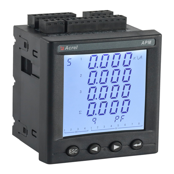
Summarization of Contents
Installation and wiring instructions
Installation dimensions
Details physical dimensions and panel opening sizes for meter installation.
Wiring method
Covers main part wiring, module parts, and signal input wiring configurations.
Engineering Construction Notes
Voltage input
Specifies voltage input requirements, including maximum voltage and fuse installation.
Current input
Outlines requirements for current input, including CT usage, phase sequence, and connection.
Communication Wiring
Describes the asynchronous RS485 communication interface and wiring.
Supply voltage
Details the conventional and P2 function supply voltage ranges for the instrument.
Operation instructions
Display description
Explains the LCD segment display and shows segment codes for characters and screen indications.
Panel description
Details the function of each key on the panel and the indicator light status for extended modules.
Display overview
Provides a hierarchical overview of the menu structure for settings and diagnosis, showing different menu levels.
Measurement Parameters
Explains how to navigate and view various electrical measurements on the display.
System Settings
System Settings Overview (SET)
Provides an overview of system settings for Bus, SYS, DLT645, and Profibus configurations.
Communication settings
Details configuring communication parameters like address, baud rate, and mode for RS485.
System setting (Current ratio)
Explains setting primary and secondary current ratios for accurate measurements.
Voltage ratio setting
Describes setting voltage ratios for PT inputs, similar to current ratio settings.
Pulse constant setting
Explains configuring the pulse constant for energy output, applicable to APM801.
Alarm Settings
Guides setting alarm groups, categories, subclasses, and action values.
Alarm Type Description
Details alarm types like overcurrent, undercurrent, and phase loss, with conditions.
Demand setting
Guides setting demand window time and period for calculating demand values.
DO settings
Explains configuring Digital Output (DO) settings, including control modes like alarm and communication.
Analog input setting
Details configuring analog input channels, including input type, decimal point, and value mapping.
Analog output setting
Guides configuring analog output channels, including output type, signal selection, and value mapping.
Time setting
Explains setting the instrument's internal clock for hour, minute, second, year, month, and day.
Network settings
Details configuration of network parameters like IP address, subnet mask, gateway, and port.
Setting of temp&humidity controlling
Guides setting temperature and humidity control parameters, including hysteresis and delays.
Recording configuration of TF card
Explains TF card recording intervals and parameters for electrical data and energy.
Ethernet Communication Guide
Ethernet Parameter Modification
Details methods for modifying Ethernet parameters via buttons or Modbus communication.
Extension of RS485 Communication
Discusses extending RS485 communication, supporting Modbus-RTU protocol only.
Modbus_TCP Communication Example (Using ModScan Software)
Illustrates Modbus TCP communication setup using ModScan for server connection.
Mail Setting
Details configuring email settings for receiving alarm notifications via email.
Modbus-TCP/IP
General communication architecture
Describes MODBUS TCP/IP architecture, including clients, servers, and interconnections.
MODBUS On TCP/IP Application Data Unit
Explains MODBUS request/response encapsulation in TCP/IP, detailing ADU and PDU.
MBAP Header descriptio
Details the fields and structure of the MBAP header used in MODBUS TCP/IP.
Example
Provides an example of establishing TCP communication from a computer to a power meter.
Correspondence between communication value and actual value
Voltage, Current, Power Factor, Frequency, Unbalance (Secondary)
Details secondary measurement correspondence for voltage, current, power factor, frequency, and unbalance.
Voltage, Current, Power Factor, Frequency, Unbalance (Primary)
Explains primary measurement correspondence for voltage, current, power factor, frequency, and unbalance.
Active power, reactive power, apparent power and energy (Secondary side; W/Var/VA/kWh)
Details secondary side power and energy value correspondence, including data formats.
Active power, reactive power, apparent power and energy (primary side; W/Var/VA/kWh)
Explains primary side power and energy value correspondence, including floating-point data format.
Harmonic data of voltage and current
Details harmonic data for voltage and current, including resolution and value correspondence.
Demand
Explains demand data format for phase currents, active/reactive power, and apparent power.
Event Record
Describes the data format for event records, including date, time, and event details.
Alarm Record
Details the data format for alarm records, including alarm group, type, value, and status.
DO Settings
Explains the format for DO settings, associating digital outputs with alarm configurations.


Need help?
Do you have a question about the APM800 and is the answer not in the manual?
Questions and answers