Table of Contents
Advertisement
Quick Links
Advertisement
Table of Contents

Subscribe to Our Youtube Channel
Related Manuals for Acrel ADW310


Summary of Contents for Acrel ADW310
- Page 1 ADW310 Wireless Energy Meter Installation and Use Manual V1.0 Acrel Co., Ltd.
- Page 2 Declaration The copyright is the property of Acrel. Any information in any paragraph or section cannot be extracted, copied or otherwise reproduced or propagated. Otherwise offenders shall take all consequences. All rights are reserved. Acrel reserves the right to modify the product specifications herein without notification.
- Page 3 Manual revision record Date Old Version New Version Modify the content 2022/8/8 V1.0 1.Writing for the first time...
-
Page 4: Table Of Contents
Catalog 1 Overview ..........................1 2 Product Model Specification And Features ................ 1 2.1 ADW310 Wireless Energy Meter Naming Rules ............1 2.2 ADW310 Wireless Energy Meter Features ..............1 3 Technical Parameters ......................2 3.1 Electrical Characteristics ....................2 3.2 Environmental Conditions ....................3 4 Dimension and Installing Description( Unit:mm) ............3... - Page 5 6.1 Communication Protocol ....................8 6.2 MODBUS Communication ....................9 6.3 Alarm Function Related Settings ................... 15 6.3.1Alarm 1 Related Parameter Register Address Table ........... 15 6.3.2Alarm 2/3 Related Parameter Register Address Table ..........17 7 Common Troubleshooting ....................19 7.1 Instrument RS485 Network Communication Failure ............ 19 7.2 Instrument Wireless Communication Failure ..............
-
Page 6: Overview
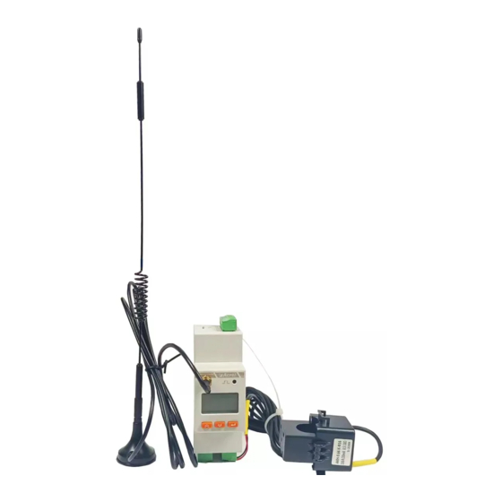
1 Overview ADW310 wireless energy meter is mainly used to measure the active energy of low-voltage network. It has the advantages of small size, high precision, rich functions, etc., and has many optional communication methods. It can support RS485 communication, Lora, 4G and other wireless communication methods. The current sampling mode of the transformer is convenient for users to install and use in different occasions. -
Page 7: Technical Parameters
RS485 interface (optional C) Communication 470MHz wireless transmission (optional LR) 4G wireless transmission (optional 4G) WIFI wireless communication (optional WF) 3 Technical Parameters Electrical Characteristics Table 2 ADW310 Electrical Characteristics Rated Voltage 220V Voltage Input Reference Frequency 50Hz Power Consumption Each phase<0.5VA... -
Page 8: Environmental Conditions
Wirelese distance in open space: 1km; 4G RS485(A、B) Interface Communication Medium Shielded Twisted Pair MODBUS-RTU、DL/T 645-07 Protocol Environmental Conditions Table 3 ADW310 Environment Conditions Operating Temperature -25℃~55℃ Temperature Range Storage Temperature -40℃~70℃ Humidity ≤95%(no condensation) Altitude <2000m 4 Dimension and Installing Description( Unit:mm) Dimension( Unit:mm) -
Page 9: Rs485 Communication Terminal, Pulse Output Terminal
Supporting CT Dimensions Table 5 Specifications and Dimensions of Supporting Transformers Perforation size Dimensions (mm) Toleranc (mm) Specification e (mm) Φ1 Φ2 AKH-0.66/K-∅10N ±1 AKH-0.66/K-∅16N Dimension Figure of Matched Current Transformer 4.2 Communication Terminal, Pulse Output Terminal Communication Interface Pulse Port 4.3 Switch Input/output Terminal The switch input is the switch signal input method, the instrument is equipped with +12V working power supply, no external power supply is required. -
Page 10: Temperature Measuring Terminal
connection is turned on or off, the on or off information is collected through the instrument switch input module and displayed locally by the instrument. The switch input can not only collect and display the local switch information, but also realize the remote transmission function through the RS485 of the instrument, that is, the "remote signal"... -
Page 11: Wiring Instructions
4.5 Wiring Instructions 5 Main Features 5.1 Measurement Function It can measure all power parameters including voltage U, current I, active power P, reactive power Q, apparent power S, power factor PF, phase angle Φ between voltage and current, frequency F, 31st harmonic, parity Total harmonic content and total harmonic content. -
Page 12: Time Sharing Function
reverse active energy, inductive reactive energy, capacitive reactive energy, and apparent energy. 5.3 Time Sharing Function Two sets of timetables, one year can be divided into 4 time zones, each set of timetables can set 12 daily time periods, 4 rates (F1, F2, F3, F4 are peaks and valleys). The basic idea of time-of-use billing is to use electric energy as a commodity, using economic leverage, the electricity price is high during the peak period of electricity consumption, and the electricity price is low when the valley is low, so as to cut the... -
Page 13: Historical Energy Statistics Function
RS485 of the instrument, that is, the "remote signal" function. 5.7 Wireless Communication Function ADW310 supports 470MHz LORA communication and 4G communication. The specific agreement on 4G communication can be obtained by contacting the relevant personnel of our company. -
Page 14: Modbus Communication
6.2 MODBUS Communication When using Modbus protocol for communication, the function code of the read data command is 03H, and the function code of the write data command is 10H. The specific register address table is as follows: Initial Address Length Data Item Name Remark... - Page 15 1027H-102DH Reserved 102EH Backlight time 0: always on 1: 1min 2:2min Year, Month Day, 102FH Time week, hour, minutes, seconds, millisecond 1034H-1035H Reserved Bit0:DO1 Bit1: DO2... 1036H DO status 0: open 1: closed Bit0:DI1 Bit1: DI2... 1037H DI status 0: open 1: closed First time zone timetable number First time zone start month, first...
- Page 16 3 Flat,4 Valley Rate, start hour, start minute Start Hour:0-23 Start Minute:1-59 The second set of timetables, 1059H Each period occupies three bytes, Same as the first set of timetables Rate, start hour, start minute The third set of timetables, 106EH Each period occupies three bytes, Same as the first set of timetables...
- Page 17 If the value is 999 then the value=999*0.001=0.999 202EH-2033H Reserved 2 decimal place 2034H Frequency If the value is 5000, Then the value=5000*0.01=50.00H 2036H- Reserved Int WIth symbol 2058H temperature 1 Unit:0.1℃ ℃ 205AH temperature 2 Int WIth symbol Unit:0.1℃ Secondary value of total active 3000H Two decimal places, Kwh...
- Page 18 Int,Unit:kWh 2 decimal place If the value is 120201, PT=10, Secondary value of total active 3014H CT=10; energy valley Then value=value*PT*CT= 120201*0.01*10*10=12020 Int,Unit:kWh 2 decimal place Forward active energy sharp If the value is 120201, PT=10, 3016H secondary value CT=10; Then value=value*PT*CT= 120201*0.01*10*10=12020 Int,Unit:kWh...
- Page 19 Then value=value*PT*CT= 120201*0.01*10*10=12020 Int,Unit:kWh 2 decimal place Forward reactive energy sharp If the value is 120201, PT=10, 3024H secondary value CT=10; Then value=value*PT*CT= 120201*0.01*10*10=12020 Int,Unit:kWh 2 decimal place Forward reactive energy peak If the value is 120201, PT=10, 3026H secondary value CT=10;...
-
Page 20: Alarm Function Related Settings
Total active power real-time Int,Unit:kW 4006H demand 3 decimal place Total forward active power Int,Unit:kW 400CH real-time demand 3 decimal place Total reverse active power Int,Unit:kW 400EH real-time demand 3 decimal place Total forward reactive power Int,Unit:kW 4010H real-time demand 3 decimal place Total reverse reactive power Int,Unit:kW... - Page 21 Bit0: Overvoltage alarm enable bit Bit1: Undervoltage alarm enable bit Bit2: Overcurrent alarm enable bit Bit3: Undercurrent alarm enable bit Bit4: Over power alarm enable bit Bit5: Under-power alarm enable bit 01DOH Alarm 1 enable bit Bit6: Whether DO1 alarm output Bit7: Whether DO2 alarm output...
-
Page 22: 2Alarm 2/3 Related Parameter Register Address Table
alarm threshold Under power 01DCH Int,Unit:0..01S alarm delay 0: Normally open DI1 initial state 01DDH 1: Normally closed 0: Do not associate with 01DEH DI1 programming 1: Associate DO1 2: Associate DO2 0: level 01E5H DO1 output mode 1: Pulse 0: Normal DO 1: total failure DO1 related... - Page 23 Bit11: Bit12: Bit13: Bit14: Bit15: Corresponding to alarm 0268H Alarm 2 Alarm status 2 enable bit Bit0: Current positive active power demand is too high alarm enable bit Bit1: Current reverse active power demand high alarm enable bit Bit2: Current high reactive power demand alarm enable bit 0217H...
-
Page 24: Common Troubleshooting
The current forward active power demand Int,Unit:kW 0238H is too high alarm 3 decimal place threshold Current reverse active 023AH power demand is too Int ,Unit:0.01S high alarm delay The current forward active power demand Int,Unit:kW 023BH is too high alarm 3 decimal place threshold Current reverse active... -
Page 25: Instrument Wireless Communication Failure
correctly 7.2 Energy Meter Wireless Communication Failure Troubleshooting suggestion: Please use the USB to 485 serial cable to connect to the RS485 interface of the instrument first, read the parameters in the meter through communication, and confirm whether the parameters in the meter are the same as the wireless configuration of the upper master station (channel and spreading factor).
Need help?
Do you have a question about the ADW310 and is the answer not in the manual?
Questions and answers