Acrel AID120 Installation And Operation Manual
Hide thumbs
Also See for AID120:
- Installation and operation manual (34 pages) ,
- Installation and operation manual (34 pages)

Subscribe to Our Youtube Channel
Related Manuals for Acrel AID120


Summary of Contents for Acrel AID120
- Page 1 Medical IT System Insulation Monitoring Devices (Five-Piece Set) Installation and Operation Manual V2.5 Acrel Co., Ltd.
- Page 2 Please read this manual carefully before using this series of products, in which the involved pictures, logos, symbols, etc. are all reserved by the Acrel Electric Co., Ltd. Personnel not inside the company shall not publicly reprint all or part of the contents without written authorization.
- Page 4 Q31/0114000129C013-2016 Insulation Monitoring Instrument” . Remove discontinued models from the five-piece set 2020.4.1 V2.3 and make adjustments and updates where necessary 2020.6.11 V2.4 Added panel installation schematic for AID120/150 2020.8.14 V2.5 Correct errors and omissions, adjust the wording Note:...
-
Page 5: Table Of Contents
2.1 Function features of AITR series medical isolation transformer ....... 2 2.2 Function features of AIM-M100 ..................3 2.3 Function features of AID120/150 ..................3 2.4 Function features of ACLP10-24 ..................4 2.5 Function features of AKH-0.66P26 current transformer ........... 4 3.Reference standard ....................... - Page 6 7.2 Introduction to the function code ................28 7.3 AIM-M10 parameter address table ..................30 8 Typical applications ......................32 8.1 Application of five-piece set of medical IT system insulation monitoring products in operating room ..................... 32 9 Power on and debugging instructions ................33 9.1 Wiring check .........................
-
Page 7: Introduction
Insulation monitoring products of medical IT system (five-piece set) include AITR series medical isolation transformer, AIM-M100 medical intelligent insulation monitor, AKH-0.66P26 current transformer, ACLP10-24 dc power module for instrument and AID series (AID120, AID150) external alarm and display instrument, etc., as shown in Table 1. -
Page 8: Function Features
It is suitable for wall installation embedded in operating room or nurse station and can monitor 1 AIM-M100 insulation monitor. It has sound and light AID120 alarm function of insulation, overload, series overtemperature and equipment failure, digital tube... -
Page 9: Function Features Of Aim-M100
2.3 Function features of AID120/150 The insulation resistance alarm value, load current alarm value and transformer temperature alarm value of the system can be set remotely. -
Page 10: Function Features Of Aclp10-24
2.4 Function features of ACLP10-24 To employ isolated linear transformer with the characteristics of strong capacity of resisting disturbance and small ripple etc. AC 220V input, DC 24V output, with max output power of 3 W. Used for the DC 24V power supply for AID series centralized alarm and display instrument and other instruments. - Page 11 / current Rated power 10000VA 8000VA 6300VA 5000VA 3150VA Rated frequency 50-60Hz 50-60Hz 50-60Hz 50-60Hz 50-60Hz Rated input AC230V AC230V AC230V AC230V AC230V voltage Rated input 45.3A 28.5A 22.5 14.2A current Rated output AC230V/115V AC230V/115V AC230V/115V AC230V/115V AC230V/115V voltage Rated output 43.5A 34.7A 27.4A...
-
Page 12: Technical Parameters Of Aim-M100 Medical Insulation Monitor
4.2 Technical parameters of AIM-M100 medical insulation monitor Refer to Table 4. Table 4 Technical Parameters of AIM-M100 Medical Intelligent Insulation Monitoring AC220V (fluctuati Voltage Thermistor PT100 ng range± Temper 10%) Auxiliary ature power Frequency 50/60Hz Measuring range -50—+200℃ measur supply Maximum ement... -
Page 13: Technical Parameters Of Aid120/Aid150
EMC electromagnetic Measuring ≤±5% compatibility/electrom Conform to IEC 61326-2-4 accuracy agnetic radiation 4.3 Technical parameters of AID120/AID150 Refer to Table 5. Table 5 Technical parameters of AID120/150 Parameter Type AID120 AID150 Auxiliary power Voltage DC 24V supply Consumption < 0.6W Display range of insulation 0—999kΩ... -
Page 14: Technical Parameters Of Akh-0.66P26 Current Transformer
4.5 Technical parameters of AKH-0.66P26 current transformer Refer to Table 7. Table 7 Technical Parameters of AKH-0.66P26 Current Transformer 0.5mA~50A Frequency 0.02-10 kHZ Input current range Output current 0.025~25 mA Loading <200Ω resistance Temperature 100 ppm/℃ Transient 200A coefficient current (1s) Phase 10... - Page 15 5.1.3 External dimensions of ACLP10-24(unit:mm) 1 2 3 4 5 6 7 Acrel DC Power Supply ACLP10-24 Type:ACLP10-24 Input:AC 220± 10% 50-60Hz Output:DC 24V 0.125A DC ON www.acrel.cn 8 9 10 11 12 13 14 Front view Side view 5.1.4 External dimensions of AID120/AID150(unit:mm)...
-
Page 16: Installation Method
A c r e l kΩ Test Mute Menu AID120 front view AID120 hole size AID120 side view A c r e l AID150 Comm AID150 front view AID150 hole size AID150 side view 5.1.5 External dimensions of AKH-0.66P26 current transformer (unit: mm) φ... - Page 17 AIM-M100 monitoring instrument. 5.2.3 Installation mode of AID series alarm and display instrument 1) The shell of AID120/150 is the same. If you choose to embed the wall for installation, the installation diagram is as follows (taking AID150 as an example):...
- Page 18 During the decoration, firstly the AID120/150 shell should be embedded in the wall to be fixed and be close to the knockouts of the pipeline, so that the wires (two power cords + a two-core shielded twisted pair) can be drawn to the front cover, and then fix the cover on the shell with screws.
-
Page 19: Wiring Method
5.3 Wiring method 5.3.1 Wiring mode of AITR series medical isolation transformer The input terminals at the transformer terminal blocks are labeled with “PM”, in which two terminals 0 and 230 are connected to the input 220V single-phase AC. The output terminals are labeled with “SEC”, in which the output voltage of two terminals 0 and 230 is AC 220V and is connected to external field load. - Page 20 18 and 19. The COM port for communication does not need wiring 5.3.3 Wiring mode of AID120/150 centralized alarm and display instrument A and B are connected with A2 and B2 in the lower terminal of AIM-M100. The terminals of the power supply correspond to the positive pole and ground of the 24V DC power module respectively.
- Page 21 RS485 communication Auxiliary power supply The 24V power supply can be connected by multiple copper wires of 2 x 1.5mm2, and the RS485 communication terminal can be connected by shielded twisted pair of 2 x 1.5mm2. 5.3.4 Wiring mode of ACLP10-24 ACLP10-24 10 11 13 14...
-
Page 22: Typical Wiring Diagram
5.4 Typical wiring diagram Note: 1) The connection line diameter of the input and output of the isolation transformer should match the rated current of the isolation transformer, or it can be selected according to the following table: Isolation transformer type Selected line diameter AITR3150 3×4mm... -
Page 23: Considerations
is connected with the 2×1.5mm wire to the No.8, 9 terminals of AIM-M100, which is not allowed for grounding. 5) In order to reliably monitor the grounding insulation of the isolation power system, the No.4, 5 terminals of AIM-M100 insulation monitor should be reliably connected to IT system (which can be connected in parallel to the output terminal of the isolation transformer) with 2×1.5mm multicore copper wires, and the No.13, 14 terminals should be respectively connected to the on-site equipotential terminals (or the grounding terminals in the isolation power cabinet) with two... -
Page 24: Programming And Application
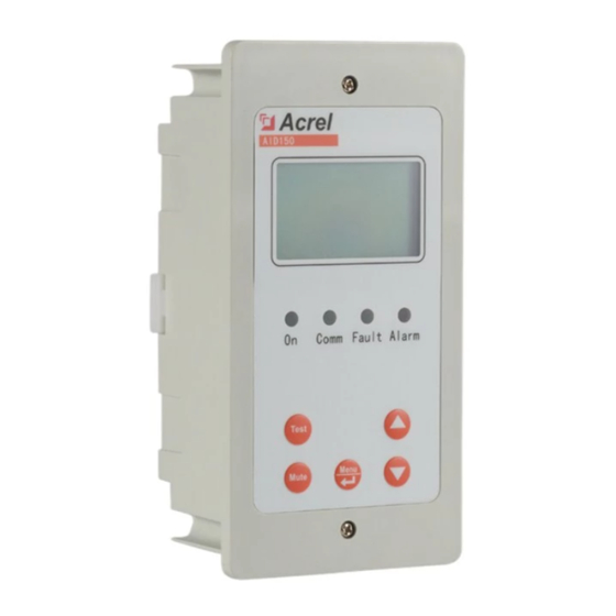
6 Programming and application 6.1 Panel description 1 2 3 4 5 6 7 8 9 10 11 12 Acrel Acrel Acrel Acrel Acrel... -
Page 25: Button Function Descriptions
Overtemp When testing transformer temperature exceeds the alarm value, or when the temperature sensor wiring is disconnected, the indicator light flashes to alarm. 6.2.2 AID120 Indicator status Instructions When the device is in normal operation, the indicator flashes, and the flickering frequency is about once a second. -
Page 26: Button Operation Descriptions
In operation state, used to start the self-test function of instrument. 6.3.2 AID120/150 The centralized alarm and display instrument has five buttons in total, namely the “Mute”button, “Menu & Enter” shared button, “” Up button, “”Down button, and “Test” button. - Page 27 6.4.2 AIM-M100 insulation monitor in programming mode (1)Enter programming mode In normal operation, press "ENTER" to enter the password input page. Press the "ENTER" key again to make the password digit reverse white display. Set the size of the anti white number through the "UP"...
- Page 28 3.Display set Enter 1.Exit Down 1.Exit Security set 2.Insulat:000KΩ 2.Insulat:000KΩ 1.Exit 1.Exit 1.Exit Up change Enter 2.Insulat:000KΩ 2.Insulat:050KΩ 2.Insulat:050KΩ 选择 Down select 选择 1.Exit 3.Display set Enter 2.Insulat:050KΩ 4.Security set Set the current alarm value to 14A, and the operation steps are as follows: 3.Display set 1.Exit 3.Current:00A...
- Page 29 4.Addr2: 001 6.Relay set 2.Addr2:001 Note: when AIM-M100 communicates with AID120, the slave address of AIM-M 100 must be set to 1, and the slave baud must be set to 9600. (7)Relay mode setting Set the normally open contact of the J1 and the J2 contacts 22 and 24 open, and close between 23 and 24.
- Page 30 6.4.3 AID120 external alarm and display key operation (1) AID120 has 5 seconds to read the host data by default when the AID120 is started. At this time, the insulation resistance value and transformer load rate display the initial value of 0. If the host data is not read for five consecutive times, the insulation resistance shows err, the transformer load rate shows err, at the same time, the sound alarm is started and all LED flickers.
- Page 31 Press Menu Enter confirm and Run status UP input password Enter to confirm Up to change value, Up or Down to Down to select bit select Enter to confirm, Up or Enter Run status Down to return (2)Current alarm value setting Taking the current alarm value 45A as an example, the setting is as follows::...
- Page 32 When the insulation monitor or residual current monitor detects the fault, AID150 displays the corresponding alarm interface and sends out the corresponding sound and light alarm. System fault(01/02) System fault(02/02) -------------------- System normal Loc.:OR Room:06 Loc.:ICU Bed:04 L1:OK L2:OK Fault type:Insu L3:OK L4:ORC 2015-07-02 12:30:45...
- Page 33 -------------------- -------------------- Input password: Press Up and Down to input password Press MENU System normal 0000 Press Enter to confirm -------------------- 2015-07-02 12:30:45 -------------------- Password Time Press Erasure to return Slave Comm Clear Firmware -------------------- -------------------- Save param settings? Press Up and Down to select YES or NO Press Enter to confirm -------------------- --------------------...
-
Page 34: Communication Protocol
Note: when aid150 is in use, the total number of Insulation Monitors and residual current monitors connected to RS485 bus should be set first, and the total number should not exceed 16 sets. This parameter is in [communication settings] in the menu. The slave address of each insulation monitor and residual current monitor shall be numbered from 1 to 16 as far as possible. - Page 35 High Low byte byte Register data High Number of byte byte register High Low byte byte CRC check High code CRC check byte byte code Low byte 7.2.2 Function code 10H: Write the registers The function code 10H allows the user to change the contents of multiple registers, which can write the time and date in this meter.
-
Page 36: Aim-M10 Parameter Address Table
written byte High 0006H byte Data to be written byte High CRC check byte code byte 7.3 AIM-M10 parameter address table Read- write Address Parameter Value range Word prope 0000H Protecting 0001-9999 (Default value is 0001) passwords 0001H high byte RS485 address1 1~247 (Default value is 1) 0001H low byte RS485 Baud1... - Page 37 0007H high byte Second 0-59 0007H low byte Reserve 0008H Insulation 10-999(Unit is KΩ) resistance 10 0009H Load current 0-500(Unit is 0.1A) 000AH Transformer -50~200(Unit is℃) temperature 000BH high byte Reserve 000BH low byte Fault type Bit0:1 Insulation resistance fault Bit1:1 Overload fault Bit2:1 Transformer overheat fault Bit3:1 L1 or L2 disconnection fault...
-
Page 38: Typical Applications
Central Intelligence Control Panel C65H ICB 16A/2P Operating Bed C65H ICB 16A/2P PC Platform DC power RS485 Alarm and display instrument AIM-M100 ACLP10-24 AID120 supply module (Installed in operating room) MED-IMD DC 24V PZ300 BG3-63II/N4DR Interpact INS 63A C65N C16/2P... -
Page 39: Power On And Debugging Instructions
Note: The grounding bat in the isolated power supply cabinet should be connected reliably with the equipotential terminals in the field. 9 Power on and debugging instructions 9.1 Wiring check For each set of IT system, the wiring check should be conducted before power on, mainly checking whether there is wrong, missed or short connection. -
Page 40: Common Faults And Eliminations
in a hand-in-hand manner, and the positive and negative are correct. 8)If each isolation transformer has a cooling fan, check whether the power control of the cooling fan is connected to the 20 and 21 terminals of AIM-M100 in the system. 9.2 Common faults and eliminations Make sure the wirings are correct and power on the system. -
Page 41: Settings And Debugging
9.3 Settings and debugging 1) When entering the menu settings, ACREL medical IT products need to enter the password. The initial password of all medical IT products is 0001. 2) After the system is powered on, set the AIM-M100 load current alarm value according to the capacity of the isolation transformer. - Page 42 Address: No.253 Yulv Road Jiading District, Shanghai, China TEL.: 0086-21-69158338 0086-21-69156052 0086-21-59156392 0086-21-69156971 Fax: 0086-21-69158303 Web-site:www.acrel-electric.com E-Mail: ACREL008@vip.163.com Postcode: 201801 Manufacturer: Jiangsu Acrel Electric Appliance Manufacturing Co., LTD. Address: No.5 Dongmeng Road, Dongmeng Industrial Park, Nanzha Street, Jiangyin City, Jiangsu Province, China TEL/Fax: 0086-510-86179970 Web-site:www.jsacrel.com Mail: JY-ACREL001@vip.163.com...
Need help?
Do you have a question about the AID120 and is the answer not in the manual?
Questions and answers