
Related Manuals for Acrel APM830


Summary of Contents for Acrel APM830
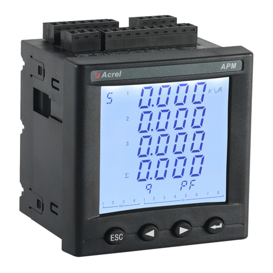
- Page 1 Power monitoring Meters APM830 Installation and Operation Instruction V1.7 ACREL CO.,LTD...
- Page 2 DECLARATION No part of this publication may be reproduced,stored in a retrieval system,or transmitted in any form by nay means,electronic,mechanical photocopying,recording,or otherwise without prior permission of Acrel. All rights reserved. This company reserve power of revision of product specification described in this manual,without notice.Before ordering,please consult...
-
Page 3: Table Of Contents
Content 1. Overview..................................1 2. Product model,specification and function........................1 2.1 Type and specification............................1 2.2 Technical Parameters............................2 3. Installation and wiring instructions..........................4 3.1 Shape and installation dimensions........................4 3.2 Security.................................5 3.3 Assembly................................6 3.4 Engineering Construction Precautions.........................6 3.4.1 Voltage input..............................6 3.4.2 Current input............................. 6 3.4.3 Communication Wiring..........................6 3.4.4 Supply voltage............................7 3.5 Wiring method..............................7... - Page 4 6.8 Multiple rate setting............................29 6.8.1 Time zone group selection setting......................30 6.8.2 Switch Switch date settings........................30 6.8.3 Meter reading day........................... 31 6.9 Recording settings.............................. 31 6.10 Demand settings............................... 32 6.11 System settings..............................33 6.12 Clear settings..............................35 6.13 version information............................35 6.14 TF card record configuration...........................
- Page 5 10.1.2 Profibus-DP physical layer........................77 10.1.3 PROFIBUS-DP Bus network structure....................78 10.2 Profibus Communication function configuration.................... 79 10.2.1 Profibus Communication variable table....................79 10.2.2 About the GSD file description......................84 11. Analysis of common fault............................85 12. Package..................................86...
-
Page 6: Overview
Dual RS485 with Ethernet interface can realize data copying of RS485 master station, eliminating the need for data switching exchange. PROFIBUS-DP interface can realize high-speed data transmission and networking function. 2. Product model,specification and function 2.1 Type and specification Type APM830 Total electrical measurement Measured Four-quadrant energy parameters Complex rate electric energy... -
Page 7: Technical Parameters
MD82 8 digital inputs + 2 digital outputs with changeover contacts (8DI+2DO) MLOG TF card storage (alarm records, event records, electrical parameters and energy timing records, etc.) MA84 8 analog inputs (class 0.5) + 4 analog outputs (class 0.5) (8AI+4AO) Extensions 1 RS485/Modbus-RTU, support master mode or slave mode 1 Profibus-DP,Configure this function to give MCM function, referred to as MCMP for short. - Page 8 Each waveform is stored at 128 cycle points; the TF card is supported to Waveform capture expand the recorded data, and the customer needs to manually pull the line chart through Excel. Dry contact inputs, built-in power supply; Switch inputs Response time: less than 300ms Contact type: open contact in main part, changeover contact in module;...
-
Page 9: Installation And Wiring Instructions
IEC 60068-2-2 Environmental Testing Part 2-2:Tests Test B:Dry heat IEC 60068-2-30 Environmental Testing Part 2-30:Tests Test Db:Damp heat , cyclic (12+12h) IEC 61000-4 Electromagnetic compatibility-Testing and measurement techniques Electrical safety in low voltage distribution systems up to 1 000V a.c. and 1 500V d.c –Equipment for testing ,... -
Page 10: Security
Note:The maximum turning angle is 90°. Multiple meter installation (unit: mm(in)) 3.2 Security CAUTION ELECTRIC SHOCK Turn off the instrument's auxiliary power and voltage inputs before installing the meter or expansion module. A B C Acrel... -
Page 11: Assembly
3.3 Assembly Insert the connection terminal into the module 2. Using a cable with a diameter of 0.2 to 0.3 mm, strip 6 mm from the end of each wire and connect it to the terminal and insert the wire into the corresponding position of the connection terminal. -
Page 12: Supply Voltage
from power cables or other strong electric-magnetic field. 3.4.4 Supply voltage The conventional power supply voltage of the instrument:AC/DC 85-265V;supply voltage with P2 funcion:AC/DC 115-415V. 3.5 Wiring method According to different design requirements, it is recommended to add a fuse (BS88 2A gG) to the power supply and voltage input terminals to meet the safety requirements of the relevant electrical specifications. - Page 13 Wiring method of signal input: 11 12 13 14 11 12 13 14 FUSES Note① FUSES Note④ Note④ 3P4W/3CT(Instrument set to 3P4W) 3P4W/3PT+3CT(Instrument set to 3P4W) 11 12 13 14 11 12 13 14 FUSES FUSES Note④ Note④ 3P3W/2PT+3CT(Instrument set to 3P3W-3CT) Note③ 3P3W/3CT(Instrument set to 3P4W) Note②...
-
Page 14: Module Parts
3.5.2 Module parts Switch module 70 77 71 72 78 73 30 31 32 33 34 继 电 器 输 出 开 关 量 输 入 Relay Output Digital Input Analog input and output module 60 61 62 63 64 65 66 67 AI1 AI 模... -
Page 15: Menu Structure Description
4.2 Menu Structure Description 4.3 navigation button character number description symbol description Menu Press this button to enter the menu interface Press this button to return to the first level menu To the right, press the button to display the cursor to move to the right one position or jump to the >... -
Page 16: Display Overview
Data increment Declining data 4.4 Display overview Second First level menu Third level menu Note level menu Line voltage average, current average, total P, positive Overview active energy Imp Maximum value Line voltage, phase voltage, deviation, angle, and Voltage minimum value average, maximum, and minimum values. - Page 17 content, voltage total odd Subharmonic content, total harmonic even harmonic content, maximum and minimum current harmonic content, and maximum and minimum voltage harmonic content Telephone waveform factor, voltage peak coefficient, factor current K coefficient Unbalance Voltage/current imbalance Vector, voltage sequence component (positive sequence, negative sequence, zero sequence), current sequence Vector component (positive sequence, negative sequence, zero...
- Page 18 needs to manually clear the data in the TF card, and clear the TF card data. For details, see the MLOG indicator of the expansion module of the 11 troubleshooting analysis is not normal.) Voltage interruption, voltage swell, voltage sag, inrush Recording record current waveform and measured value No TF Card :...
-
Page 19: Interface Introduction
swell, voltage sag, voltage interruption threshold setting, voltage harmonics, DI trigger Demand setting Demand sliding window, cycle setting Language, password, backlight, contrast, extreme System settings self-clearing time, imbalance algorithm, time setting Clear power, clear demand, clear extremes, clear alarm and switch records, clear transient waveform recording Clear settings language, password,... -
Page 20: View Data Information
5. View data information 5.1 Viewing event records 5.1.1 View DIDO records On the main screen, press Menu to enter the menu interface, press ∨ until “Event Log” is highlighted, and press √ to display the event log. Press ∨ until “DIDO Record” is highlighted, press √ to display the DIDO record. - Page 21 can record 66 kinds of alarms, which are divided into 13 kinds of alarm categories (AT01 APM series of meters overcurrent, AT02 undercurrent, etc., see Table 1). Each alarm category contains several alarm subclasses (such as AT01 overcurrent classification alarm with A). Phase overcurrent, B phase overcurrent, C phase overcurrent, etc., see Table 1).
- Page 22 Total active overpower AT05 (Overpower) Total reactive overpower Total apparent overpower Total active underpower AT06 (Underpower) Total reactive underpower Total apparent underpower Overdemand alarm of active power AT07 (Demand alarm) Underdemand alarm of active power Total over power factor AT08 (Power factor alarm) Total under power factor Over THD of Phase A current Over THD of Phase B current...
-
Page 23: View Transient Records
Current Loss Voltage Loss Phase Reversal 5.1.3 View transient records: The types of transient events are: voltage swell, voltage sag, voltage interruption and inrush current. The threshold setting of the transient alarm event can be changed to the “Occurrence Setting” in “Parameter Setting” . After the transient event occurs, the meter saves the corresponding transient event record, including the transient event action time, reset time and transient event type, to help you quickly analyze and solve the power quality problem. - Page 24 Note: Alarm status: Swell Pickup is triggered by alarm and Swell dropout is recovered by alarm. Alarm data: Open the Alarm folder, the folder contains the sub-folder named “Year_Month” (for example: 2018_02), and the sub-folder contains the .csv record file named “Alarm Type” (eg: Over THD) .csv), you can view the alarm data.
- Page 25 “Year_Month_Date” The file (eg 2018_03_31.csv) can be used to view the timed electrical parameter record data. The log file is as follows: Note: The meter records 1 electric parameter data (primary side) by default for 1 minute, the time interval can be set, and the time interval unit is minute.
-
Page 26: Parameter Setting
6. Parameter setting 6.1 Parameter setting interface The parameter setting interface is divided into the following parts: input setting, communication setting, alarm setting, DO setting, AI setting, AO setting, multi-rate setting, recording setting, demand setting, system setting, clear setting, version information. 6.2 Input settings On the main interface, press Menu to enter the menu interface, press ∨... - Page 27 Setting up projects Range Explain Setting Basis The setting must be correct reflect actual connection method of the 3P4W detection point. The wrong Phase line 3P3W-3CT Current instrument wiring mode wiring mode setting will 3P3W-2CT cause the data measured by the device to be completely wrong.
-
Page 28: Communication Setting
Total merit, According to user needs total reactive Set the energy pulse type of the 17 and 18 Pulse 1 output settings, default power, total pulse output terminals always active. vision 1s/imp、 Set the type of 19, 20 pulse output terminals. 0.01kwh、... -
Page 29: Alarm Settings
1st check digit No parity, 2 stop bits, odd parity, even parity 1200,2400,4800,9600,19200,38400 2nd baud rate 2nd check digit No parity, 2 stop bits, odd parity, even parity Profibusaddress 1~126 DLT645 address 0~999999999999 DLT645 Leader Add None(No preamble)、Add 4 0xfc(Add 4 0xFC) Automatic acquisition IP Close, open Modbus TCP port... - Page 30 value 0~9999 Alarm delay value, in seconds Action delay Alarm recovery value, unit and decimal point Reset threshold -9999~9999 position are consistent with the meter display value Alarm recovery delay value, accurate to the 0~9999 Reset delay second Zero alarm switch Open close Zero alarm enable, valid when low alarm Alarm description:...
-
Page 31: Do Settings
Examples are as follows: Set Phase A overcurrent alarm of the first group of alarm enabled. Action value: The action value is a primary value. For example, if the alarm value is set to 5.500A, when Phase A current value exceeds 5.500A, the alarm condition is triggered and the timer starts. Action delay time: When the alarm condition is triggered, if Phase A current value exceeds 5.500A, an alarm record will be generated after the setted delay time (accurate to the second), Alarm group (alarm 1), alarm type (Phase A overcurrent), alarm time (eg: 2017-5-12 14:15:20) will be recorded. -
Page 32: Ai Setting
communication control It is valid when communication control. When set to Communication control 0, it is the level control mode. When it is not 0, it is 0~9999s self-breaking delay the pulse control mode. After the delay setting time is disconnected, the unit is s. Alarm corresponding to See alarm type description DO enable... -
Page 33: Ao Setting
Analog input signal corresponding Decimal point 0000 000.0 00.00 0.000 value decimal point 100% Analog input high point signal Corresponding -9999~9999 -999.9~999.9 -99.99~99.99 -9.999~9.999 corresponds to the high point value value of the parameter Analog input signal -9999~9999 -999.9~999.9 -99.99~99.99 -9.999~9.999 Corresponding corresponds to the low value of the... -
Page 34: Multiple Rate Setting
Determined based AO output low point corresponding parameter value Corresponding value associated signal Note Analog output selection corresponding parameter Serial parameter parameter Serial number parameter parameter number SB (B phase apparent IA (Phase A current) PA (A phase active power) power) SC (C phase apparent IB (Phase B current) -
Page 35: Time Zone Group Selection Setting
6.8.1 Time zone group selection setting 14 time periods can be set for each time 4 time zone groups can be set Each time period is divided into 14 intervals, as described in the table below. Serial number time select description 00:00 level... -
Page 36: Meter Reading Day
Switch the date setting, up to 6 date segments, as described in the table below. Serial number date select description 01-01 Indicates that the multi-rate energy is calculated using time period 1 from January 1 to March 1. 03-01 Indicates that the multi-rate electric energy is calculated using time period 2 from March 1 to May 1. -
Page 37: Demand Settings
Setting item range Description The current threshold (the nominal current multiplied by this parameter) affecting the inrush current event affects the judgment electric shock 105.0~200.0% result of the inrush current event, and the stricter the power quality requirement is, the smaller the value is. When the sag event is judged, the real-time voltage RMS value is required to be higher than the threshold value (nominal voltage Voltage rise... -
Page 38: System Settings
press √ to enter the demand setting interface. Press ∧ or ∨ to switch the item of demand setting, press Enter to enter the setting of the item, press + or - to change. After the change is completed, press Exit, enter the password in the pop-up window, press SaveExit to save the changes and exit, press Esc to exit without saving the changes. - Page 39 Setting item range description Change instrument language Chinese, English, the factory default setting is Chinese display language 0000~9999,The factory default is 0001, customers can modify Change original password the settings themselves. If you forget your password, you need password and change it. to contact me.
-
Page 40: Clear Settings
Display format year, Time yy-mm-dd hh:mm:ss month, day, hour, minute, second Off (default is off) Overview, current line voltage, current current, frequency, total After 1 minute without any power, active power demand, active energy, reactive energy, operation, the meter jumps apparent energy, total forward rate power, total reverse rate Default interface back to the main interface,... -
Page 41: Tf Card Record Configuration
corner of the meter. 6.14 TF card record configuration .Read the data in the TF card using a card reader on the computer 2. Double-click to open APM800Config.ini. 3. [INTERVAL] is a configuration area of sampling interval. Parameter (minute), indicates the recording interval of electrical parameter in minutes and range (1-30). Energy (hour), indicates the recording interval of energy in hours and range (1-12). - Page 42 System Type Int16 (RW) Lower 7 bit: 0:3P3W_2CT, 1:3P4W, 2:3P3W_3CT Int16 (RW) 1A or 5A Nominal Secondary Current Nominal Secondary Voltage L-L Int16 (RW) 100V、110V、400V、690V Nominal Primary Current Int16 (RW) 1-32760A Nominal Primary Voltage L-L Int32 (RW) 100V-1200KV Int16 (RW) Baud rate(COMM2,slave) 0:38400 1:19200...
- Page 43 33-35 Gateway address Int32 (RW) Eg:192.168.1.1。 Address34:C0A8H;Address35:0101H Int16 (RW) 0~9999 Port Number IP address allocation Int16 (RW) (DHCP) Manual Automatic : ;1: Set IP mode Int16 (RW) code: 0XABCD Int16 (RO) 0,0x11:No TF module or no card 0x22:TF card error 0x33:TF card is normal SD Storage State 0x44:...
- Page 44 Demand cycle 1~60 Maximum data time 0~5express different meanings 0:keep 1:monthly recalculation 2:data recalculation 3:recalculation every hour 4:recalculation every 30 minute 5:recalculation every 15 minute Shock electric 0.1% 1000~9999 (999.9%) Voltage rise 0.1% 1000~9999 (999.9%) Voltage dip 0.1% 100~1000 (100.0%) Loss voltage 0.1% 0~500 (50.0%)...
- Page 45 275-276 Total apparent power 0.01VA Int32 (RO) Secondary side A phase power factor 0.001 Int16 (RO) B phase power factor 0.001 Int16 (RO) C phase power factor 0.001 Int16 (RO) Power factor 0.001 Int16 (RO) 300-301 Positive active energyEPI Int32 (RO) Secondary side 302-303 Reverse active energy EPE...
- Page 46 Current angle between IB and 0.1° 1115 Int16 (RO) Current angle between IC and 0.1° 1116 Int16 (RO) 1117-1119 ABC current deviation 0.1% 1120-1121 A phase voltage 0.1V Int32 (RO) Primary 1122-1123 B phase voltage 0.1V Int32 (RO) Primary 1124-1125 C phase voltage 0.1V Int32 (RO)
- Page 47 1170-1171 Apparent power,phase C 0.01VA Float (RO) Primary 1172-1173 Apparent power,Total 0.01VA Float (RO) Primary ABC voltage and current 1174-1176 angle 1179 frequency 0.01Hz Int16 (RO) Primary 1180 Power factor,phase A 0.001 Int16 (RO) Primary 1181 Power factor,phase B 0.001 Int16 (RO) Primary 1182...
- Page 48 minute Reactive Power Demand 1216-1219 Same total active power MAX,Total Real Power Demand MAX , 1220-1223 Same total active power Total 1250-1251 Current demand,phase A 0.001A Int32 (RO) Primary 1252-1253 Current demand,phase B 0.001A Int32 (RO) Primary 1254-1255 Current demand,phase C 0.001A Int32 (RO) Primary...
- Page 49 UInt16 1303 Alarm recovery value Primary. Range :0~9999 (RW) UInt16 range:0~9999 1304 Delay time of Recovery (RW) The first group of other alarm settings: refer to Phase A overcurrent alarm 1305 1310 1315 Phase B overcurrent alarm Phase C overcurrent alarm Maximum overcurrent alarm 1320 Neutral overcurrent alarm...
- Page 50 1765 1770 1775 Maximum overcurrent alarm Neutral overcurrent alarm Phase A undercurrent alarm 1780 1785 1790 Phase B undercurrent alarm Phase C undercurrent alarm Minimum undercurrent alarm Maximum current unbalance 1795 1800 1805 Neutral undercurrent alarm alarm Current loss alarm 1810 1815 1820...
- Page 51 Low byte indicates DI/DO number。 2201 UInt16 High byte:Year; Low byte: Month Year、Month (RO) 2202 UInt16 High byte: Day ; Low byte: Hour Day、Hour (RO) 2203 UInt16 High byte:Year; Low byte:Second Minute、 second (RO) Other event records: Refer to event record 1 2204 2208 2212...
- Page 52 15376-16143 Power factor alarm event 16144-16911 Total harmonic alarm event 16912-17679 Total even harmonic alarm event 17680-18447 Total odd harmonic alarm event 18448-19215 Digital input alarm event 19216-19983 Other alarm events Register Description Unit Data Type Note (WORD) 2500 UInt16 (RW) Function selection of relay 0: Remote control;...
- Page 53 Associated alarm configuration Associated alarm configuration of Associated alarm configuration 2746 2758 2770 of relay 14 relay 15 of relay 16 Associated alarm configuration Associated alarm configuration of Associated alarm configuration 2782 2794 2806 of relay 17 relay 18 of relay 19 Associated alarm configuration Associated alarm configuration of Associated alarm configuration...
- Page 54 current in month this month occurrence Day and hour 3503 Int16 (RO) High byte: Day; Low byte: Hour of occurrence Minute 3504 Int16 (RO) second High byte: Minute; Low byte: Second occurrence Maximum Phase Same as maximum of Phase A current in this 3505-3509 current in this month month...
- Page 55 Minute 3569 Int16 (RO) second High byte: Minute; Low byte: Second occurrence Maximum of Phase B active Same as maximum of Phase A active power in 3570-3574 power in this month this month Maximum of Phase C active Same as maximum of Phase A active power in 3575-3579 power in this month this month...
- Page 56 Day and hour 3628 Int16 (RO) High byte: Day; Low byte: Hour of occurrence Minute 3629 Int16 (RO) second High byte: Minute; Low byte: Second occurrence Phase B power factor 3630-3634 Same with Phase A power factor in this month this month Phase C power factor 3635-3639...
- Page 57 Minimum of Phase B Minimum of Phase C Minimum of average 3710 3715 3720 voltage in this month voltage in this month voltage in this month Minimum of AB line Minimum of BC line Minimum of CA line 3725 3730 3735 voltage in this month voltage in this month...
- Page 58 last month last month last month Minimum of neutral current in Minimum of average current in Minimum of Phase A voltage in 4055 4060 4065 last month last month last month Minimum of Phase B voltage in Minimum of Phase C voltage in Minimum of Phase C voltage in 4070 4075...
- Page 59 4878 Total odd harmonic distortion 0.01% Int16 (RO) (TOHD) of Phase A current 4879 0.01% Int16 (RO) TOHD of Phase B current 4880 TOHD of Phase C current 0.01% Int16 (RO) 4881 TOHD of Phase A voltage 0.01% Int16 (RO) 4882 TOHD of Phase B voltage 0.01%...
- Page 60 transmissi selection (1:4-20mA, transmission type, on output 2:0-20mA, 3:1-5V, phase A current is selected 4:0-5V) signal. Low Byte: Signal corresponding value of Selection (Refer to the high point is 5000, Table corresponding System Setup value of the low point is Analog Output 0, and the actual decimal...
- Page 61 Register Description Unit Data Type Note (WORD) High byte: Input For example: 4-20mA is type (1:4-20mA, selected for the input 2:0-20mA, 3:1-5V, type , and decimal point Input type 4:0-5V) is 3 digits. The display 5600 Int16 (RW) decimal point Byte: value of input high point display...
-
Page 62: Correspondence Between Communication Value And Actual Value
7.3 Correspondence between communication value and actual value It is agreed that Val_t is the communication readout value and Val_s is the actual value. 7.3.1 Voltage, Current, Power Factor, Frequency, Unbalance (Secondary The series of measured values are read with 03 command of the Modbus-RTU communication protocol. Each item occupies 1 word. The correspondence between the communication value and the actual secondary measurement value is shown in the following table: Applicable parameters Resolution... -
Page 63: Active Power, Reactive Power, Apparent Power And Energy (Primary Side; W/Var/Va/Kwh)
MODSCAN ,the communication read-out value is 1 at address 253 and 26000 at address 254, that is ,Val_t=1×65536+26000=91536, then Val_s = Val_t*0.01 = 915.36W. For example: To read positive active energy IMP, the data can be read at address 300-301 MODSCAN in Int16eger reading mode by MODSCAN , the communication read-out value is 0 at address 300 and 19000 at address 301, that is, Val_t=0x65536+19000=19000, then Val_s =Val_t*1=19000Wh=19kWh. -
Page 64: Harmonic Data Of Voltage And Current
For example: To read phase A active power PA, the data can be read at address 1150-1151 in Floating Pt reading mode by MODSCAN,the read-out value Val_t=110000, then Val_s =Val_t*0.01=1100W. For example: To read phase positive active energy IMP, the data can be read at address 3050-3051 in Floating Pt reading mode by MODSCAN,the read-out value Val_t=589000, then Val_s =Val_t*1=589000Wh=589kWh. -
Page 65: Alarm Record
0x11 0x01 0x16 0x0D 0x38 0x20 Content Switch 0:DO 0:Open Year Month Hour Minute Second number 1: Closed 1:DI Closed Analysis DO1 changed from open to closed at 14:56:32 on January 22,2017. 7.3.8 Alarm Record The data format of the alarm record is as follows: Address1 Address2 Address3... - Page 66 Associated with the alarm number 31 of Associated with the alarm number 0 of And so the first group (Alarm of over active the first group (phase A overcurrent power) alarm) (1: valid; 0: invalid) Address Address3 Address4 INT32 … Content Associated with the alarm number 32 Associated with the alarm number 63 of...
-
Page 67: Ethernet Communication Guide
INT32 … Associated with the alarm number 31 of Associated with the alarm number 0 of ...and so the first group (Alarm of over active the first group (phase A overcurrent power) alarm) The remaining addresses in this example are all 0 and are no longer listed. If the current DO1 function is controlled by the alarm of the first group, in this example, DO1 is associated with the phase A overcurrent alarm, the phase B overcurrent alarm, and the phase C overcurrent alarm of the first group. -
Page 68: Extension Of Rs485 Communication
Connect the Ethernet module and the computer with a twisted-pair B cable, power the meter. If the local connection on the bottom right corner of the computer monitor is connected at this point, you can continue to the next step. Otherwise, power off the meter, check the network cable and network settings. - Page 69 The contents of the following address table are for Modbus TCP operation only. (Related to the slave information read by the user) Register Resoluti Data type (Read-write Name Note (WORD) attribute) 39992-39993 Group 32-1 slave status Int32 (RO) The high byte is first, the low byte is after, bit0 is the first group state, and 1 is the read failure, and the corresponding cache is cleared.
-
Page 70: Extending Rs485 Communication As Modbus Master
58800-58928 Number UInt16(RO) The cumulative number of transmissions transmissions used to debug slave access E.g: The settings are as follows: The first group slave station address is 1, the start address is set to 0, the communication length is 125, the second group slave station address is 2, the start address is 20, and the communication length is 125, the read information area 40000-40124 corresponds to the information of the first group of slave station addresses 0-125, 40125-40249 corresponds to the information of the second group of slaves station 20-144, and so on, when the communication length of the 128 groups of devices is 125,... -
Page 71: Dl/T-645 Communication Guide
9. DL/T-645 Communication Guide It mainly describes how to use the software to control the series of instruments through the communication port. Mastering the content requires you to have a knowledge base of the DL/T645-2007 agreement and read through all the other sections of this volume to gain a comprehensive understanding of the product features and application concepts. - Page 72 code identification code )Frame starter 68H Identifies the beginning of a frame of data, the value is 68H Address field A0~A5 The address field consists of 6 bytes (8-bit binary code) with 2 bits of BCD code per byte. The address length can be up to 12 decimal digits.
-
Page 73: Data Identification Table
Each communication is initiated by the primary station transmitting a request command frame to the slave selected by the information frame address field, and the requested slave responds according to the requirements of the control code in the command frame. Response delay after receiving the command frame :≤500ms Pause time between bytes... - Page 74 Power factor block 68 01 00 00 00 00 00 68 11 04 33 32 39 35 B9 16 X.XXX Total active energy 68 01 00 00 00 00 00 68 11 04 33 33 33 33 B2 16 XXXXXX. Positive active energy 68 01 00 00 00 00 00 68 11 04 33 33 34 33 B3 16 XXXXXX.
- Page 75 Last February, positive active rate, 68 01 00 00 00 00 00 68 11 04 35 37 34 33 B9 16 XXXXXX. valley energy Last February Positive active energy 68 01 00 00 00 00 00 68 11 04 35 32 34 33 B4 16 XXXXXX.
- Page 76 energy Last June, positive active rate, flat 68 01 00 00 00 00 00 68 11 04 39 36 34 33 BC 16 XXXXXX. energy Last June, positive active rate, valley 68 01 00 00 00 00 00 68 11 04 39 37 34 33 BD 16 XXXXXX.
- Page 77 Last October, positive active rate, sharp 68 01 00 00 00 00 00 68 11 04 3D 34 34 33 BE 16 XXXXXX. energy Last October, positive active rate peak 68 01 00 00 00 00 00 68 11 04 3D 35 34 33 BF 16 XXXXXX.
- Page 78 hhmm Perceptual reactive maximum demand 68 01 00 00 00 00 00 68 11 04 33 33 36 34 B6 16 XX.XXXX and time of occurrence YYMMDD hhmm Capacitive reactive maximum demand 68 01 00 00 00 00 00 68 11 04 33 33 37 34 B7 16 XX.XXXX and time of occurrence YYMMDD...
- Page 79 Phase A voltage 1st harmonic content 68 01 00 00 00 00 00 68 11 04 34 34 3D 35 C0 16 XX.XX Phase A voltage 2nd harmonic content 68 01 00 00 00 00 00 68 11 04 35 34 3D 35 C1 16 XX.XX Phase A voltage 3rd harmonic content 68 01 00 00 00 00 00 68 11 04 36 34 3D 35 C0 16 XX.XX...
- Page 80 B phase voltage waveform distortion 68 01 00 00 00 00 00 68 11 04 33 35 3B 35 BE 16 XX.XX Phase C voltage waveform distortion 68 01 00 00 00 00 00 68 11 04 33 36 3B 35 BF 16 XX.XX Phase A current waveform distortion 68 01 00 00 00 00 00 68 11 04 33 34 3C 35 BE 16...
- Page 81 time hhmm and day … 68 01 00 00 00 00 00 68 11 04 36 … 33 38 … 16 (previous time) instantaneous freezing 68 01 00 00 00 00 00 68 11 04 34 33 34 38 B9 16 YYMMDD Year, time...
-
Page 82: Profibus-Dp Guide
(Last 12 times) instantaneous freezing 68 01 00 00 00 00 00 68 11 04 3F 33 34 38 C4 16 YYMMDD Year, month time hhmm and day … 68 01 00 00 00 00 00 68 11 04 3F … 34 38 … 16 10. -
Page 83: Profibus-Dp Bus Network Structure
shielded twisted pair cable, the longest communication distance is 9.6km (requires additional relay), and the maximum length is 90km when using fiber optic cable. The maximum cable length of each segment of Profibus-DP is related to the transmission rate. Different media, different baud rates, and different distances that signals can be transmitted are shown in Table 7. -
Page 84: Profibus Communication Function Configuration
VP(Pin 6) B-line(Pin 3) A-line(Pin 8) DGND(Pin 5) Figure 2 PROFIBUSCable terminator for cable (pin number of 9-pin D-type connector) Profibus's bus terminator consists of a pull-up resistor and a pull-down resistor. When there is no station transmitting data on the bus (ie idle time), these two resistors force different state voltages to a certain value, thus ensuring that there is on the bus. - Page 85 Input data parameter name remark type word Address table [00]:High 8 bits, reserved [01]:Low 8 bits Bit7-Bit2:reserved Bit0: D01 Output switch quantity 1 [00][01] 1、2 Output switch state DO 2 word Bit1: D02 Output switch quantity 2 [02][03] So on... Bit31: DO32 Output switch quantity Bit0: DI1 Output switch quantity 1 Bit1: DI2 Output switch quantity 2...
- Page 86 [28][29] Secondary 15、16 Total active power P total 2 word Active power, [30][31] side Reactive power, [32][33] Total reactive power Q Secondary 17、18 inspecting power 2 word [34][35] total side Decimal points: 2 [36][37] Secondary 32-bit signed 19、20 Total apparent power S 2 word [38][39] side...
- Page 87 [66][67] side EQL [68][69] Secondary 35、36 Reverse reactive energy 2 word [70][71] side EQC [72][73] Secondary side electrical energy 37、38 Positive total active energy 2 word [74][75] Decimal points: 3 32-bit signed [76][77] Positive tip active energy 2 word 39、40 [78][79] [80][81] 41、42...
- Page 88 parameter outpu Numerical range Remarks name 01]Low 8 digits 0:disconnect Bit0: DO1 [00][01] Bit1: DO2 1:closure Bit2-Bit7: Reserved Control(word) [00]High 8 Bit15: permission When this bit is 1, it is valid for the operation of bit0 modification enabled and bit1. When 0, the operation is invalid. Bit14-Bit8: Reserved Note: PROFBUS-DP V0 is a cyclic data exchange.
-
Page 89: About The Gsd File Description
The calculation result in the above example is: 10.2.2 About the GSD file description GSD File access: The instrument's GSD file can be downloaded from the company's website at www.acrel.cn or from our customer service. CD mode is sent with the product When configuring the PROFIBUS master station, after loading the GSD file of the APM series instrument, the user parameters adopt the default values and do not need to be changed, as shown in the figure below. -
Page 90: Analysis Of Common Fault
APM8xx 11. Analysis of common fault Fault content Analysis Check whether the power supply voltage is in the working voltage range. Continue to malfunction, after disconnecting the power supply (refer to 3.3 assembly for No display on power details), re-insert the main body and the module, restart the instrument after 1 minute, if the fault is not eliminated, you need to contact our company for repair;... -
Page 91: Package
(anti-counterfeit label), installation and operating instructions. When opening the product packaging, please check carefully for damage. If there is any damage, please inform ACREL company or agent in time, and please keep the damaged outer packaging, the company will replace it in time. - Page 92 Address: No.253 Yulv Road Jiading District, Shanghai,China TEL.: 0086-21-69158338 0086-21-69156052 0086-21-59156392 0086-21-69156971 Fax: 0086-21-69158303 Web-site: www.acrel-electric.com E-mail: ACREL008@vip.163.com Postcode: 201801 Manufacturer: Jiangsu Acrel Electrical Manufacturing Co., LTD. Address: No.5 Dongmeng Road,Dongmeng industrial Park, Nanzha Street,Jiangyin City,Jiangsu Province,China TEL./Fax: 0086-510-86179970 Web-site: www.jsacrel.com Postcode: 214405 E-mail: JY-ACREL001@vip.163.com...
Need help?
Do you have a question about the APM830 and is the answer not in the manual?
Questions and answers