
Related Manuals for Acrel ACR10R Series


Summary of Contents for Acrel ACR10R Series
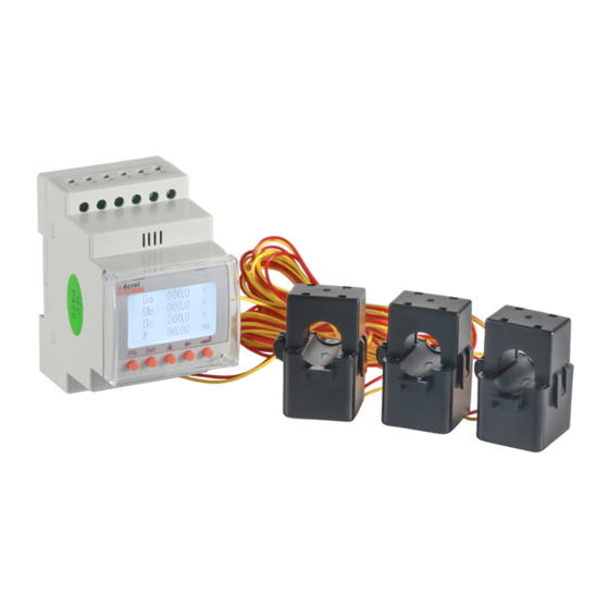
- Page 1 External Roche Coil and Switched Transformer Harmonic Meter V1.5 Installation and operation instruction ACREL CO., Ltd.
- Page 2 Please read the instructions carefully before using this product.The picture,labels and symbols involved are all owned by Acrel Co.,Ltd. Any person who is not an employee of the company shall not publicly reprint all or part of the contenes without written authorization.
- Page 3 CONTENT Note:the instrument must be installed on site with the supporting open and closed transformer or roche coil...- 2 - 1. General..................................- 2 - 2.Size of product.................................- 2 - 3.Product function..............................- 2 - 4.Technical parameter..............................- 3 - 5.Installation................................- 5 - 5.1 Shape and installing size (unit:mm)......................- 5 - 5.2 Size of open type transformer(unit:mm)....................- 5 - 5.3 installation...............................
- Page 4 Example: Read the number of years, MODSCAN in HEX reading mode can be read directly in the address bar 0X0081..........................- 37 - 7.5.6Event record............................- 37 - 8 DL/T-645Communication Guideline........................- 38 - 8.1 DL/T645-1997 protocol overview........................ - 38 - 8.2Transmission mode............................- 38 - 8.3Protocol................................- 39 - - 1 -...
-
Page 5: Product Function
Note:the instrument must be installed on site with the supporting open and closed transformer or roche coil. 1. General The guide-rail harmonic meter with external roche coil and open type mutual inductor is suitable for energy saving renovation projects in high energy consumption industries such as smelting,steel,electric welding,semiconductor,etc.And also for power monitoring of distributed photovoltaic grid-connected cabinet,power demand side management and other applications.The utility model has the advantages of no need to remove primary bus,simple and convenient wiring,safe... - Page 6 Active power/reactive ■ power/apparent power Four quadrant electric ■ energy measurement Maximum demand □ Multiple rate electric □ energy measurement Power Total harmonic content ■ quality subharmonic (2-31 times) ■ monitoring Data logging Incident record □ Alarm □ Built-in clock □...
- Page 7 Output mode:Open-collector photocoupler pulse,two way output Electric energy Output Pulse constant:4000、8000imp/kWh Three-phase Communication RS485 interface,Modbus-RTU Protocol Display mode input Four way dry contact input Switching Output mode: two way relay nO contact output Function output Contact capacity:AC 250V/3A、DC 30V/3A Measuring accuracy Frequency0.05Hz、reactive electric energy1class、other 0.5class Power supply AC85~265V or DC100~350V;...
-
Page 8: Installation
5.1 Shape and installing size 5.Installation (unit:mm) 5.2 Size of open type transformer (unit:mm) Φ10mm Φ16mm Φ24mm Φ36mm 5.3 installation Instrument installation method:DIN 35mm standard guide rail installation Close in the direction of the Positive arrow pole( white) Negative pole( black) Direction of current - 5 -... -
Page 9: Method Of Connection
Installation method of open and close type mutual induction Positive pole(red) Negative pole(white) Roche coil mounting method 5.4Method of connection (Note:in case of any inconsistency with the wiring diagram on the meter housing,the wiring diagram on the meter housing shall prevail) According to different design requirements,it is recommended to add fuses in the power supply and voltage input terminals to meet the safety requirements of relevant electrical codes 12 13... - Page 10 When three-phase three-wire connection is made,no.2 terminal and no.4 terminal shall be externally connected together The fuse in the wiring diagram is recommended 0.5A or 3A. When the instrument is installed on site,it must correspond to the supporing open and closed transformer or roche coil one by one,otherwise the measurement accuracy will be affected,and the connection between the two must be reliable.
- Page 11 6.2.1Power parameter interface Phase voltage Line voltage Current 000.0 000.0 000.0 000.0 000.0 000.0 000.0 000.0 000.0 00.00 00.00 1.000 Active power Reactive power 00.00 00.00 kvar 00.00 00.00 kvar 00.00 00.00 kvar 00.00 00.00 kvar Apparent power Power Power factor 00.00 00.00 1.000...
- Page 12 Total harmonic content Harmonic measurement interface 谐波测量界面 数值显示 VALUE 00.00 00.00 00.00 00.00 00.00 00.00 Subharmonic content 00.00 00.00 00.00 00.00 00.00 00.00 00.00 00.00 00.00 00.00 00.00 00.00 After selecting the harmonic parameters,the meter enters the interface of harmonic parameters by pressing the enter key.At this time,the harmonic data is in the state of anti-white.Press the enter key to view the voltage and current harmonic data.
- Page 13 6.2.3 Electric energy display interface Four quadrant electric energy METER This month EPI 0000000.00 kwh 000000.00 HARM STEUP EPE 0000000.00 kwh 000000.00 ENERG 000000.00 EQI 0000000.00 kwh 000000.00 EQE 0000000.00 kwh 000000.00 The month before last compound rate Last monthundefineds compound Total compound rate active of active electricity rate of active electricity...
- Page 14 After selecting the event record,the instrument presses the enter key to display the action information of the switch input and output.As shown in the figure above,the record of Article 1 indicates the input score of the first switch at 8:31:26 on March 5,16;Aritcle 5 records indicate that the first switch input at 12:32:26 on March 5,16 years,press the upper and lower keys to view other records,and save a total of 16 records.
- Page 15 and does not need to be set up In.PU Primary voltage value Unit:kV In.PI Primary current value customer according actual current CODE Password settin Default 0001 Give an example: Customer ordering model:voltage:10KV/100V,current:600A/5A,at this time,U RANGE shall be set to 100V,IN.PU is set to 10KV,ang IN.PI is set as 600. 6.2.6.2communication setting Config A OUT...
- Page 16 12:00 In the12:00~14:00 time period,the rate is peak 14:00 In the14:00~16:00 time period,the rate is flat 16:00 In the16:00~22:00 time period,the rate is flat 22:00 In the22:00~00:00 time period,the rate is sharp 6.2.6.4Switch setting Config A OUT BAND Comm Timer 0000 0010 Tarrif...
- Page 17 Neutral Voltage Current line unbalance unbalance current Output delay time In case of DO output mode, set as 0, potential control mode; set as non 0 pulse control mode, disconnection after delay set time, unit: 1 second; No action interval BAND Scope of high alarm value -9999~9999 (decimal point not considered) AL.Hi...
-
Page 18: Communication Wiring
进入用户设置界面后, Press the up and down keys to select the time setting,and then press Enter to enter the setting interface.After entering the time setting interface,press the up and down keys to select the item to be set,and press the left and right keys to modify the setting item value. Note:illegal time cannot be saved(for example,illegal time cannot be entered at 25:05 on January 5,2008) 6.2.4.7Other setting Config... - Page 19 It's recommended that the matching resistance shall be added between the foremost and instruments A, B and the rated resistance range is 120Ω~10 kΩ. Wiring for other settings: 7.1Transmission mode Two-core shielded line/shielding layer is connected with ground. The information is transmitted asynchronous and in bytes,and the communication information transmitted between the host and the slave is in a 10-bit word format, including 1 start bit,8 data bits(the smallest valid bit is sent first),no 7.2Information frame format parity check bit.1 stop bit,set to parity bit or 2 bit stop bit,11 bit word format.
- Page 20 numerical value,a reference address,or a setting value.For example,the function code tells the terminal to read a register,the data area needs to indicate whichregister to start from and howmany data to read,and the embedded address and data vary according to the type and the content between the slave machine.
- Page 21 Function code Function code High byte Byte number Start address Low byte High byte underrange Register data High byte Low byte underrange Number of registers Low byte High byte underrange Register data Low byte Low byte underrange CRC check code High byte High byte underrange...
- Page 22 7.4Communication application details In the design of the instrument,the communication address table is unified.According to the following introduction,the user can conveniently realize the functions of telemetry,remote communication,remote control and so on. 7.4.1Communication description Communication of ACR Harmonic meters adopt MODBUS-RTU Communication protocol, MODBUS protocol define check code, data sequence etc.
- Page 23 secondary side coefficient Primary side and secondary 16-17 Float mould side coefficient of current Power,primary and secondary 18-19 Float mould side coefficients Multi-rate time period 1 21-23 Multi-rate time period 2 24-26 Information about multi-rate:8 time period、4 Multi-rate time period 3 27-29 rates;...
- Page 24 Second Event record 1 retain 143-148 Event record 2 retain 149-154 Event record 3 retain 155-160 Event record 4 retain 161-166 Event record 5 retain 167-172 Event record 6 retain 173-178 Event record 7 retain 179-184 Event record 8 retain 185-190 Event record 9 retain...
- Page 25 Secondary side power decimal , Point Phase C Active power Pc 257-258 digital:2,unit:W Secondary side power decimal , Point Total.Active power PTotal 259-260 digital:2,unit:W Secondary side power decimal , Point Phase A Reactive power Qa 261-262 digital:2,unit:var Secondary side power decimal , Point Phase B Reactive power Qb 263-264 digital:2,unit:var...
- Page 26 This month active Flat Electric Secondary side Electric energy 335-336 energy 2-bit decimal Point,unit:kWh This month active Valley Secondary side Electric energy 337-338 Electric energy 2-bit decimal Point,unit:kWh This month active Total Electric Secondary side Electric energy 339-340 energy 2-bit decimal Point,unit:kWh Last month active...
- Page 27 Backward reactive Electric Secondary side Electric energy 371-372 energy EQC 2-bit decimal Point,unit:kWh A Phase Voltage 2-31 order A Phase Voltage 2-31 order harmonic;2-bit 373-402 harmonic ratio decimal point B Phase Voltage 2-31 order A Phase Voltage 2-31 order harmonic;2-bit 403-432 harmonic ratio decimal point...
- Page 28 C Phase Current sampling C Phase Current sampling point 719-750 point(32 point/wave) High bytes DI (bit 0 as DI1, bit 1 as DI2, like DIDO state this, bit 7 as DI8), low bytes DO (bit 0 as 1000 DO1, bit 1 as DO2, like this, bit 7 as DO8) 0-32, details given in correlation in table First way alarm selection 1001...
- Page 29 Second way transmission 1043-1045 Third way transmission 1046-1048 Fourth way transmission 1049-1051 DLT/645 address 1100-1102 0--4800bps; 4--2400bps 1--9600bps; 5--1200bps Second way communication 1103 2--19200bps; speed 3--38400bps(default communication speed). 0--no calibration bit(default mode); Second way communication 1--odd calibration bit; 1104 calibration mode 2--even calibration bit.
- Page 30 energy in January points Historical active peak electric Same as above 1252-1253 energy in January Historical active flat electric Same as above 1254-1255 energy in January Historical active trough electric Same as above 1256-1257 energy in January Historical total active electric Same as above 1258-1259 energy in January...
- Page 31 Phase voltage 2-63 Phase C voltage 2-63 harmonic; decimal 2124-2185 harmonic content points: 2 Phase A current 2-63 harmonic Phase A current 2-63 harmonic; decimal 2186-2247 content points: 2 Phase B current 2-63 harmonic Phase B current 2-63 harmonic; decimal 2248-2309 content points: 2...
- Page 32 Generation time: High 8: year ; low 8: month 3011 year、month Generation time: High 8: day ; low 8: hour 3012 day,hour Generation time: High 8: minutes ; low 8: seconds 3013 minutes, seconds phase voltage Ubnmaximum primary side 3014 Generation time: High 8: year ;...
- Page 33 year、month Generation time: High 8: day ; low 8: hour 3032 Generation time: High 8: minutes ; low 8: seconds 3033 minutes, seconds Phase Current Iamaximum primary side 3034 Generation time: High 8: day ; low 8: hour 3035 year、month Generation time: High 8: day ;...
- Page 34 Generation time: High 8: day ; low 8: hour 3052 day,hour Generation time: High 8: minutes ; low 8: seconds 3053 minutes, seconds C active power Pc maximum primary side 3054 Generation time: High 8: year ; low 8: month 3055 year、month Generation time:...
- Page 35 Generation time: High 8: year ; low 8: month 3071 year、month Generation time: High 8: day ; low 8: hour 3072 day,hour Generation time: High 8: minutes ; low 8: seconds 3073 minutes, seconds Total.Reactive power primary side 3074 QTotalmaximum Generation time: High 8: year ;...
- Page 36 Generation time: High 8: minutes ; low 8: seconds 3089 minutes, seconds TotalApparent power primary side 3090 STotalmaximum Generation time: High 8: year ; low 8: month 3091 year、month Generation time: High 8: day ; low 8: hour 3092 day,hour Generation time: High 8: minutes ;...
- Page 37 year、month Generation time: High 8: day ; low 8: hour 3108 day,hour Generation time: High 8: minutes ; low 8: seconds 3109 minutes, seconds Maximum current of neutral Secondary side Current decimal 3110 line Point digital:3 Generation time: High 8: year ; low 8: month 3111 year、month Generation time:...
- Page 38 minutes, seconds Phase Current Total A Phase Current Total harmonic 3126 harmonic distortionmaximum content;decimal point digital:2 Generation time: High 8: year ; low 8: month 3127 year、month Generation time: High 8: day ; low 8: hour 3128 day,hour Generation time: High 8: minutes ;...
- Page 39 table: Applied parameter Relation Unit VoltageUan、Ubn、Ucn、Uab、Ubc、Uca Val_s=Val_t * PU / Ue CurrentI 、I 、I Val_s=Val_t * PI / 1000 Power factor PF None 、PF 、PF 、PF Val_s=Val_t / 1000 总 Frequency FR Val_s=Val_t / 100 Example 1:Read a phase voltage UAN,read the data stored in the address 243 colimn to read the data,that is,the communication read out value Val_t=3800,read PU=100,Ue=400,so Val_s=...
- Page 40 Applied parameter Relation Unit Crest factor None Val_s=Val_t / 1000 THFF None Val_s=Val_t / 100 Current K factor None Val_s=Val_t / 100 Peak voltage(Secondary side value) Val_s=Val_t / 10 Unbalance factor of Voltage and current Percentage Val_s=(Val_t / 10)% Example:Read A phase Voltage wave peak coefficient,communication reading value “Val_t” is 1414 at address 0×0119,then Val_s =Val_t / 1000=1414/1000=1.414 7.5.4Voltage/current harmonic data This series measuring value is read out by Modbus-RTU protocol 0×03 command,each item occupy...
-
Page 41: Transmission Mode
14:56:32,the value is 172.2V,the corresponding register value is asfollows: High 8-bit Low 8-bit Adress 1 Adress 2 Adress 3 Adress 4 Adress 5 Adress 6 1722 8 DL/T-645Communication Guideline It mainly specifies how to resort to the software to control the instrument series via the communication port. The user shall have knowledge of DL/T645-1997 Communication Protocol and thoroughly read all other contents herein before a relatively comprehensive understanding on the functions and applications of the product. - Page 42 8.3Protocol When the data frame arrives at the terminal equipment, it resorts to one simple "port" to access the retrieved equipment. Such equipment will erase data frame "envelop" (data header) and read data. If there is no error, execute the assignment required by the data. And then, it will add the generated data into the obtained "envelop"...
- Page 43 Data field byte length; read data L≤200, write data≤50, L =0 means there is no data field e)Error calibration CS The sum of modulus 256 of all bytes starting from the frame begin symbol to calibration code, namely binary arithmetic sum of all bytes is no more than 256 overflow value. f) symbol 16H Indicate the end of one frame of data9.3.2 Transmission a)Lead byte...
- Page 44 electric energy Backward passive 68 99 99 99 99 99 99 68 01 02 53 C4 80 16 XXXXXX.XX kvarh electric energy Phase A voltage 68 99 99 99 99 99 99 68 01 02 44 E9 96 16 Phase B voltage 68 99 99 99 99 99 99 68 01 02 45 E9 97 16 Phase C voltage 68 99 99 99 99 99 99 68 01 02 46 E9 98 16...
-
Page 45: Switch Output
power Phase B reactive XX.XX kvar 68 99 99 99 99 99 99 68 01 02 75 E9 C7 16 power Phase C reactive XX.XX kvar 68 99 99 99 99 99 99 68 01 02 76 E9 C8 16 power Conjuction power 68 99 99 99 99 99 99 68 01 02 83 E9 D5 16... - Page 46 Fax: (86)021-69158303 Service hotline: 800-820-6632 URL: www.acrel.cn E-mail:ACREL001@vip.163.com Zip code: 201801 Production base: Jiangsu Acrel Electrical Equipment Manufacturing Co., Ltd. Address: No.5, Dongmeng Road, Dongmeng Industrial Park Zone, Nanzha Town, Jiangyin City. Tel(Fax):(86) 0510-86179970 Zip code: 214405 E-mail:JY-ACREL001@vip.163.com Change record: V1.3 :1、...
Need help?
Do you have a question about the ACR10R Series and is the answer not in the manual?
Questions and answers