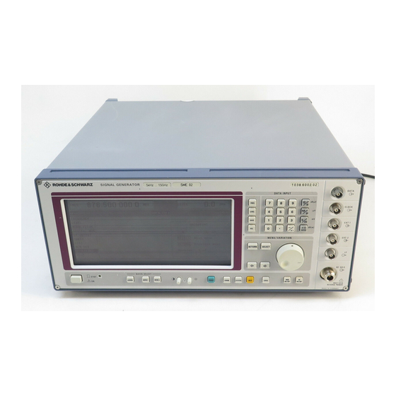
Summarization of Contents
Customer Support
Technical support – where and when you need it
Provides expert help on equipment operation, programming, and applications via Customer Support Centers.
Up-to-date information and upgrades
Offers subscription to electronic newsletters and requests for information/upgrades via email.
Feedback
Encourages users to provide comments on support needs via email.
USA & Canada
Lists contact details, hours, and email for support in USA and Canada.
East Asia
Lists contact details, hours, and email for support in East Asia.
Rest of the World
Lists contact details, hours, and email for support globally, excluding specific regions.
Supplement B to Operating Manual SIGNAL GENERATOR SME
Correction of Data Sheet, Number 757.0358.23
Provides corrections or updates to the original data sheet, referencing a specific number.
Models SME03 and SME03E
Details amplitude modulation specifications for SME03 and SME03E models.
Model SME06
Provides amplitude modulation frequency response specifications specific to the SME06 model.
Model SME03A and SME models fitted with option SM-B50
Lists specifications for SME03A and SMExx models with SM-B50, focusing on high-speed processor improvements.
1 Preparation for Use
1.1 Putting into Operation
Covers initial setup steps like covers, ventilation, signal levels, and instrument connections.
1.2 Functional Test
Covers the instrument's self-test routines for ROM and RAM contents and important functions.
1.3 Fitting the Options
Explains how to fit and recognize new options, and the need to clear CMOS RAM after configuration changes.
1.4 Mounting into a 19" Rack
Details mounting the instrument into a standard 19-inch rack using an adapter, emphasizing air inlet and outlet.
2 Operation
2.1 Explanation of Front and Rear Panel
Details the elements of the front and rear panels of the instrument.
2.2 Operating Concept
Explains the instrument's operating principles, display design, and menu structure.
2.2.2 Basic Operating Steps
Details how to operate the instrument by calling menus, selecting parameters, and using keys.
2.2.3 Basic Operating Steps
Covers selecting parameters, changing values via input or rotary knob, and triggering actions.
3 Remote Control
3.1 Introduction
Introduces IEC-bus and RS-232 interfaces for remote control and SCPI support.
3.2 Brief Instructions
Provides short sequences for fast instrument operation via IEC-bus and RS-232.
3.3 Switchover to Remote Control
Explains how the instrument switches to remote control and how to return to manual operation.
4 Maintenance and Troubleshooting
4.1 Maintenance
Covers basic maintenance procedures like cleaning the instrument and storage.
4.1.1 Cleaning the Outside
Provides instructions for cleaning the instrument's exterior using a soft cloth, avoiding solvents.
4.1.3 Exchange of the Lithium Batteries
Details the procedures and cautions for exchanging the instrument's CMOS-RAM and XMEM lithium batteries.
5 Performance Test
5.1 Test Instruments and Utilities
Lists the necessary test instruments and utilities required for performance testing.
5.1.1 Standard Test System
Outlines the test equipment and setup for measuring modulation characteristics using a standard system.
5.1.1.2 Test System with Audio Analyzer
Outlines the test equipment and setup for measuring modulation characteristics using an audio analyzer.
5.2 Test Procedure
Details the procedure for testing the generator's rated specifications after warm-up and calibration.
Annex A IEC/IEEE Bus Interface
Characteristics of the Interface
Lists key characteristics of the IEC/IEEE bus interface, including data transfer and handshake.
Bus Lines
Explains the data bus lines (DIO 1 to DIO 8) and their transmission format.
Interface Functions
Lists and describes interface functions (SH1, AH1, L4, T6, SR1, PP1, RL1, DC1, DT1) for remote control.
Annex B List of Error Messages
SCPI-Specific Error Messages
Explains SCPI-specific error codes, their text, and general error explanations.
Command Error - Faulty command
Details error codes related to faulty or invalid commands, syntax, parameters, and data types.
Execution Error - Error in executing the command
Lists error codes for issues during command execution, such as trigger ignored or settings conflict.
Annex C List of Commands
:ABORt:DM
Command to abort the single execution of a DM list.
:CALibration:LEVel[:DATA]?
Command to query the level correction data, returning all data in the specified format.
[:SOURce]:AM[:DEPTh]
Command to set the modulation depth in percent.
Annex D Programming Examples
1. Including IEC-Bus Library for QuickBasic
Includes the necessary IEC-bus library for QuickBasic programming.
2. Initialization and Default Status
Describes bringing the IEC bus and instrument settings to a default status using subroutines.
3. Transmission of Instrument Setting Commands
Provides an example of setting output frequency, level, and AM modulation, including step width.


Need help?
Do you have a question about the SME03 and is the answer not in the manual?
Questions and answers