
Related Manuals for Arista DCS-7170-64C


Summarization of Contents
Chapter 1: Overview
1.1 Scope
Lists supported Arista Networks Data Center Switches.
1.2 Receiving and Inspecting the Equipment
Instructions for checking shipments for damage and verifying contents.
1.3 Installation Process
Outlines the main steps required for switch installation.
1.4 Safety Information
Directs users to external documents for safety warnings and compliance.
1.5 Obtaining Technical Assistance
Provides contact methods for technical support and resources.
1.6 Specifications
Lists technical specifications for supported Arista Data Center switches.
Chapter 2: Preparation
2.1 Site Selection
Criteria for choosing a suitable location for switch installation.
2.2 Reconfiguring Air Flow
Instructions for changing the fan and louver orientation for airflow.
2.3 Tools and Parts Required for Installation
Lists tools and parts needed for switch installation.
2.4 Electrostatic Discharge (ESD) Precautions
Guidelines to prevent ESD damage during installation and servicing.
Chapter 3: Rack Mounting the Switch
3.1 Two-Post Rack Mount
Procedure for mounting the switch in a two-post rack, including bracket attachment and rack insertion.
3.2 Four-Post Rack Mount
Procedure for mounting the switch in a four-post rack, covering rail assembly and switch attachment.
Chapter 4: Cabling the Switch
4.1 Grounding the Switch
Instructions for connecting the switch to the data center ground.
4.2 Connecting Power Cables
Guidelines for connecting AC and DC power cables to the switch.
4.3 Connecting Serial and Management Cables
Information on connecting console and Ethernet management cables.
Chapter 5: Configuring the Switch
5.1 Manual Configuration
Steps to manually configure the switch, bypass ZTP, and set basic parameters.
Appendix A: Status Indicators
A.1 Front Indicators
Information on system, fan, and power supply status LEDs on the front panel.
A.2 Rear Status Indicators
Information on fan and power supply status LEDs on the rear panel.
Appendix B: Parts List
B.1 Rack Mount Parts
Lists components included in the accessory kit for rack mounting.
B.2 Cables
Lists included power and adapter cables for the switch.
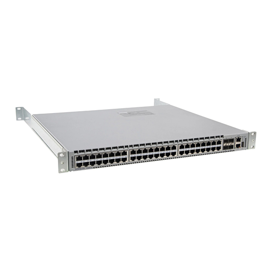
Appendix C: Front Panel
C.1 Port-Speed Groups
Explains the port grouping feature for flexible Ethernet speed configuration.
C.2 Front Panels
Displays diagrams of the front panel layouts for various switch models.
Appendix D: Rear Panel
Rear Panel Layouts
Displays diagrams of the rear panel layouts for various switch models.
Appendix E: Regulatory Model Numbers
Regulatory Model Numbers and Product Numbers
Lists Regulatory Model Numbers (RMNs) for the switches covered in this guide.
Appendix F: Taiwan RoHS Information
Taiwan RoHS Information
Provides Taiwan RoHS compliance information and a link to a table.
Need help?
Do you have a question about the DCS-7170-64C and is the answer not in the manual?
Questions and answers