Table of Contents
Advertisement
Quick Links
5453 Great America Parkway
Santa Clara, CA 95054
USA
© Copyright 2014 Arista Networks, Inc. The information contained herein is subject to change without notice. Arista Networks
and the Arista logo are trademarks of Arista Networks, Inc in the United States and other countries. Other product or service names
may be trademarks or service marks of others.
7xxx-xx Series Quick Start Guide
Quick Start Guide
Data Center Switch
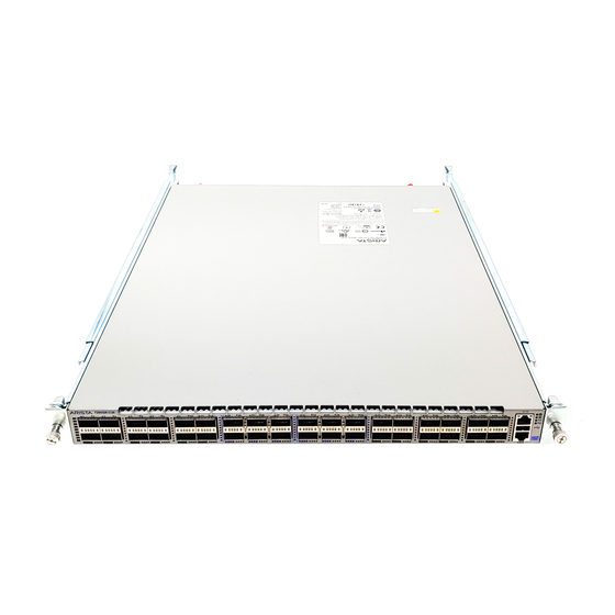
DCS-7280QR-C36
Regulatory Model AN1508
Arista Networks
www.arista.com
Headquarters
Support
408 547-5502
866 497-000
support@arista.com
408 547-5500
www.arista.com
Sales
408 547-5501
866 497-0000
sales@arista.com
Preliminary
Advertisement
Table of Contents

Related Manuals for Arista DCS-7280QR-C36


Summary of Contents for Arista DCS-7280QR-C36
- Page 1 © Copyright 2014 Arista Networks, Inc. The information contained herein is subject to change without notice. Arista Networks and the Arista logo are trademarks of Arista Networks, Inc in the United States and other countries. Other product or service names may be trademarks or service marks of others.
-
Page 2: Chapter 1 Overview
Chapter 1 Overview 1.1 Scope This guide is intended for properly trained service personnel and technicians who need to install the following Arista Networks Data Center Switches: DCS-7280QR-C36 Important! Only qualified personnel should install, service, or replace this equipment. -
Page 3: Safety Information
Refer to the Arista Networks document Safety Information and Translated Safety Warnings available at: http://www.arista. com/en/support/docs/eos Obtaining Technical Assistance Any customer, partner, reseller or distributor holding a valid Arista Service Contract can obtain technical support in any of the following ways: ... -
Page 4: Chapter 2 Preparation
Chapter 2 Preparation Site Selection The following criteria should be considered when selecting a site to install the switch: Temperature and Ventilation: For proper ventilation, install the switch where there is ample airflow to the front and back of the switch. The ambient temperature should not go below 0° or exceed 40° C. Important! To prevent the switch from overheating, do not operate it in an area where the ambient temperature exceeds 40°C (104°F). -
Page 5: Tools Required For Installation
Other Requirements: Select a site where liquids or object s cannot fall onto the equipment and foreign objects are not drawn into the ventilation holes. Verify these guidelines are met: — Clearance areas to the front and rear panels allow for unrestricted cabling. —... -
Page 6: Chapter 3 Rack Mounting The Switch
Chapter 3 Rack Mounting the Switch Important! The rack mounting procedure is identical for all switches covered by this guide. Illustrations in this chapter depict the mounting of DCS-7280QR-C36 switch. The accessory kit provides components for installing the switch in two-post and four-post racks. ... -
Page 7: Attaching Mounting Brackets To The Chassis
3.1.1 Attaching Mounting Brackets to the Chassis This procedure attaches mounting brackets to the switch chassis (Figure Step 1 Align the mounting brackets with the attachment pins to obtain the desired mounting position. Step 2 Place the bracket flush on the chassis with attachment pins protruding through key-openings. Step 3 Slide the bracket toward the front flange until the bracket clip locks with an audible click. -
Page 8: Four-Post Rack Mount
Four-Post Rack Mount The switch is mounted onto a four-post rack by assembling two rails onto the rear posts, sliding the switch onto the rails, then securing the switch to the front posts. The installation kit provides the following four-post mounting parts: ... - Page 9 Figure 7: Improper Bracket Mount Example for Four-Post Rack Mount 3.2.1 Attaching Mounting Brackets to the Chassis Figure 8 displays the front bracket alignment for mounting the switch into a four post rack. Figure 8: Attaching the Mounting Brackets to the Switch Chassis This procedure attaches mounting brackets to the switch chassis as depicted by Figure Step 1...
- Page 10 3.2.2 Assembling the Rails onto the Equipment Rack Rail-rods and rail-slides assemble into two identical rails. Each rail connects a front post to a rear post. When the rails are installed, the switch slides on the rails into the rack. Each bracket includes a screw that attaches the switch to the rail.
- Page 11 Figure 11: Attaching the Rails 3.2.3 Attaching the Switch to the Rack After the rails are installed, the switch slides on the rails into the rack. Each bracket includes a thumb screw that attaches the switch to the rail Step 1 Lift the switch into the rack and insert the mounting brackets into the slide rails. Figure 12: Inserting the Switch onto the Rails Step 2 Slide the switch on the rails, toward the rear posts, until the mounting bracket flanges are flush...
-
Page 12: Chapter 4 Cabling The Switch
Figure 13: Attaching the Switch to the Rack Posts After completing the four-post rack mount, proceed to Chapter 4: Cabling the Switch. Chapter 4 Cabling the Switch Grounding the Switch After mounting the switch into the rack, connect the switch to the data center ground. Figure 14 displays the location of the grounding pads located on the bottom corners of the front panel. -
Page 13: Connecting Power Cables
Connecting Power Cables Important! Installation of this equipment must comply with local and national electrical codes. If necessary, consult with the appropriate regulatory agencies and inspection authorities to ensure compliance. The switch operates with two installed power supplies. At least one power supply must connect to a power source. -
Page 14: Connecting Serial And Management Cables
DB-9 The front panel contains the console, management, and USB ports. Figure 16 displays the ports on the DCS-7280QR-C36 Switch. Figure 16: Front Panel Ports Connect the front panel ports as follows: Console (Serial) Port: Connect to a PC with the RJ-45 to DB-9 serial adapter cable. -
Page 15: Chapter 5 Configuring The Switch
Chapter 5 Configuring the Switch Arista switches ship from the factory in Zero Touch Provisioning (ZTP) mode. ZTP configures the switch without user intervention by downloading a startup configuration file or a boot script from a location specified by a DHCP server. To manually configure a switch, ZTP is bypassed. The initial configuration provides one username (admin) accessible only through the console port because it has no password. -
Page 16: Appendix A Status Indicators
Front panel LEDs are located on the right side of the chassis and display system, fan, and power supply status. Figure 17 shows DCS-7280QR-C36 front panel LEDs Figure 17: System Status Indicators Table 3: System Status LED States LED State... -
Page 17: Port Indicators
Port Indicators Port LEDs, located in the vicinity of their corresponding ports, provide link and operational status. Figure 18 displays the Port LED location on the DCS-7280QR-C36 switches. Figure 18: Port LEDs Table 6 provides status conditions that correspond to port LED states. Port LED behavior for QSFP+ and SFP+ ports is consistent. - Page 18 Rear Status Indicators Fan and power supply modules are accessed from the rear panel. Each fan and power supply module contains an LED that reports the module status. The Fan Status LEDs are on the fan modules, as displayed in Figure 19 Figure 19: Fan Status LED Table 7: Fan Status LED States...
-
Page 19: Parts List
Appendix B Parts List Each switch provides an accessory kit that contains parts that are required to install the switch. The following sections list the installation parts contained in the switch accessory kit. Rack Mount Parts Table 9 lists the items provided in the accessory kit. Table 9: Rack Mount Parts Quantity Description... - Page 20 Description Power cables: IEC-320/C13-C14, 13 A, 250V, 2 meter RJ-45 Patch Panel Cable, 2 meter RJ-45 to DB9 Adapter Cable, 2 meter Warning! All provided power cables are for use only with Arista products 警告 すべての電源コードは提供する製品で使用するためだけを目的としている。 電源コードの他の製品での使用の禁止 Arista が提供するすべての電源コードは、Arista の製品でのみ使用してください。...
Need help?
Do you have a question about the DCS-7280QR-C36 and is the answer not in the manual?
Questions and answers