
Related Manuals for Arista DCS-7280CR3K-96


Summarization of Contents
Overview
Scope
Lists the Arista Networks Data Center Switches supported by this guide.
Receiving and Inspecting the Equipment
Details procedures for checking shipment for damage and verifying contents.
Installation Process
Outlines the sequential tasks required for switch installation.
Safety Information
Provides crucial safety guidelines and directs to external documentation.
Obtaining Technical Assistance
Lists contact methods for technical support and accessing resources.
Specifications
Details physical dimensions, weight, operational, and storage specifications.
Preparation
Site Selection
Criteria for choosing an installation site, including ventilation and temperature.
Reconfiguring Air Flow
Instructions for changing the airflow direction of fans and PSUs.
Tools and Parts Required for Installation
Lists the necessary tools and parts for installing the switch.
Electrostatic Discharge (ESD) Precautions
Guidelines to prevent damage from static electricity during handling.
Rack Mounting the Switch
Two-Post Rack Mount
Detailed steps for mounting the switch in a two-post rack system.
Four-Post Rack Mount
Detailed steps for mounting the switch in a four-post rack system.
Cabling the Switch
Grounding the Switch
Procedures for properly grounding the switch to the data center ground.
Connecting Power Cables
Instructions for connecting AC and DC power supplies to the switch.
Connecting Serial and Management Cables
Details on connecting console, USB, and Ethernet management ports.
Configuring the Switch
Manual Configuration Steps
Steps to bypass ZTP, set password, IP address, and default route.
Appendix A: Status Indicators
Front Indicators
Explains the status LEDs on the front panel of the switch.
Rear Status Indicators
Explains the status LEDs on the rear panel, for fan and power modules.
Appendix B: Parts List
Rack Mount Parts
Lists the components included for rack mounting the switch.
Cables
Lists the types and quantities of cables provided with the switch.
Appendix C: Front Panel
Port-Speed Groups
Describes port grouping for flexibility in configuring Ethernet speeds.
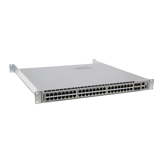
Front Panels
Visual diagrams of the front panels for various switch models.
Appendix D: Rear Panel
Models Without Separation Between Fans 1 and 2
Shows the rear panel layout for models without fan separation.
Models With Ground Attach Point Between Fans 1 and 2
Shows the rear panel layout with a ground attach point.
Models With Separation Between Fans 1 and 2 (no ground)
Shows the rear panel layout for models with fan separation.
Appendix E: Regulatory Model Numbers
Regulatory Model Numbers and Product Numbers
Lists the Regulatory Model Numbers (RMNs) for the described product models.
Need help?
Do you have a question about the DCS-7280CR3K-96 and is the answer not in the manual?
Questions and answers